An I/Q Modulator for Wireless Applications
RF Prime Corp.
Sacramento, CA
The model RFIQ-19-SM20 is one of a new family of I/Q modulators designed and manufactured using the patented Blue Cell process. The modulator is designed for use in wireless communication systems in the personal communications service (PCS) frequencies of 1850 to 1910 MHz (transmit) and 1930 to 1990 MHz (receive). Also available in this product line are modulators designed for use in the 1800 MHz European digital communications system (DCS), 900 MHz cellular communication systems and wireless local loop systems in the 2400 MHz industrial, scientific and medical (ISM) band. The bidirectional nature of the design allows the devices to be used as both modulators and demodulators.
Responding to several large original equipment manufacturers' requests to provide a low cost, highly repeatable I/Q modulator with sideband carrier suppression unavailable previously in a small surface-mount component, the design goals of 10 dB (max) conversion loss, carrier rejection greater than 25 dB, sideband suppression greater than 30 dB and third-harmonic suppression better than 40 dB were attained easily using the in-house design techniques for thick-film, multilayer, planar technology. The modulator measures approximately 0.50" square and 0.13" high. The low profile, compact size makes this family ideally suited to satisfy the ever-increasing demand to reduce size, weight and cost of communication base stations. Figure 1 shows the modulator's ceramic package.
 Fig. 1: The modulator in a ceramic package.
The obvious advantages of the Blue Cell II family of I/Q modulators are low cost and small size. The cost is actually one-third that of comparable units from other manufacturers, and the small-size footprint is approximately one-half the size of these same units. One not-so-obvious advantage of this modulator is the unit-to-unit repeatability due to the Blue Cell design and production techniques. The circuit patterns are designed on a computer so they can be stepped and repeated to create a mask for large circuit arrays. These arrays are manufactured in lots of 500 or more, depending on demand.
The Blue Cell Process
Blue Cell is a combination of existing proven manufacturing processes and a new design approach. The name Blue Cell originated from the color of the most commonly used dielectric material incorporated in the layers of the first mixers. The thick-film planar circuit designs are laid out and constructed using a readily available design and simulation software package. The baluns, resistor networks and ground planes are designed in multiple layers with dielectric material sandwiched in between. The need for ferrite cores wound with wire has been eliminated. The magnetic structure required for mixer and power splitter performance is achieved through the layers of the Blue Cell product. The multiple layers are fired onto an alumina substrate. The diodes are then die attached to the circuits automatically and wire bonded while still in an array. Other process steps include diode encapsulation, lead attach, lidding, marking and final test. All of the manufacturing is automated to reduce labor costs and further increase reliability. Mixers and power splitters using the Blue Cell designs have been manufactured for over two years, and this complete family of modulators as well as a Blue Cell transformer have been introduced recently.
Electrical Performance
The important electrical specifications of an I/Q modulator are carrier suppression, undesired sideband rejection, and third- and fifth-harmonic product suppression. Performance of the modulator in these parameters can be enhanced by applying either external capacitors or some small amount of bias voltage to the I and Q ports.
Using a combination of well-defined RF models, close attention to layout symmetry and a repeatable assembly process, performance levels similar to monolithic ICs have been achieved. This performance has been obtained by careful package and electrical design, without using subharmonic injection or other novel approaches.
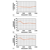
Improvements in the area of 10 dB are typical using these tuning techniques. The design goals also included simplicity and ease of use. Although these tuning techniques may be applied, they are not necessary to achieve the performance shown in Figure 2 . The modulator's frequency bandwidth is specified over the areas of common usage: cellular, PCS and ISM. However, the modulator actually operates over a 1000 MHz bandwidth.
 Fig. 2: The I/Q modulator's (a) conversion loss, (b) sideband suppression and (c) carrier suppression.
Applications for this family of I/Q modulators include PCS and cellular base stations, Japanese Personal Handyphone, North American Digital Cellular and satellite systems. Other frequency schemes can be accommodated as well, such as the European DCS systems. The Global System for Mobile communications in Europe is also a candidate for the modulator at 1800 MHz. Applications such as code-division or time-division multiple access cellular base stations that modulate digital signals into RF frequencies use I/Q modulators. Wireless local area networks and wireless local loops at 2400 MHz also require I/Q modulators with good sideband rejection. Price: less than $10 in volume quantities (10,000).
RF Prime Corp.,
Sacramento, CA (916) 368-4400.
