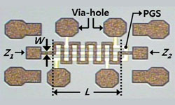
Figure 1 Meander line employing a PGS.
Using a meander line employing a periodic ground structure (PGS) on GaAs substrate, a highly miniaturized impedance transformer was developed for application to low impedance matching. Its size is 0.151 mm2, which is 3.5 percent of the size of a conventional microstrip line impedance transformer on GaAs substrate. The meander line impedance transformer showed a good RF performance in the S/C band.
In wireless communication systems, low impedance transformation is required for impedance matching between active devices, because the input and output impedances of the active devices are much lower than 50 Ω in the microwave band.1Therefore, for an efficient impedance matching of microwave devices employed in wireless communication systems, an impedance transformer performing low impedance transformation between active devices is indispensable and should be highly miniaturized for integration in monolithic microwave integrated circuits (MMIC).
In this work, a highly miniaturized meander line impedance transformer, employing a periodic ground structure on GaAs substrate, was developed for application to low impedance matching components on MMICs.
A Meander Line Employing PGS
In order to develop a highly miniaturized impedance transformer, a meander line employing PGS with a high capacitive element is used. Figure 1 shows the structure of the meander line employing PGS. As shown, the PGS was inserted at the interface between a SiN film and the GaAs substrate and was electrically connected to the backside ground metal through the via-holes. As is well known, a conventional microstrip line without PGS has only a periodical capacitance Caper unit length, but the meander line employing PGS hasanadditional capacitance Cbas well as Ca, due to PGS. Cbis an additional capacitance between the meander line and PGS, which is caused by the SiN film between meander line and PGS. Therefore, using the meander line with PGS, a short wavelength and low impedance transformer can be realized, due to an increase of capacitance, because Z0and λgare inversely proportional to the periodic capacitance. In other words, Z0= √L/Ca nd λg= 1 / [ f×√LC].2Table 1 shows the measured Z0and λgof a meander line employing PGS and a conventional microstrip line without PGS, which were fabricated on a GaAs substrate with a height of 100 μm. As shown in Table 1, the meander line employing PGS exhibits a much lower Z0and a shorter λg than the conventional microstrip line. The width of the PGS pattern (T) and line width (W) were set to 20 μm, and the line width of the conventional microstrip line is 20 μm. The wavelength was measured at 4.5 GHz. The results indicate that highly miniaturized and low impedance passive circuits can be realized by using the meander line employing PGS.


Figure 2 Photograph of the meander line impedance transformer employing PGS on a GaAs substrate.
A Miniaturized Meander Line Impedance Transformer Employing PGS on GaAs MMIC
Figure 2 shows a photograph of the meander line impedance transformer employing PGS on a GaAs substrate. The characteristic impedance Z0of the impedance transformer is given by Z0=√(Z1× Z2),2 where Z1and Z2are the source and load impedance, respectively. In this work, Z1and Z2are 5 and 20 Ω, respectively. Therefore, the Z0of the meander line impedance transformer is 10 Ω. For an operating frequency of 4.5 GHz, the circuit length of the meander line impedance transformer employing PGS is 0.43 mm and the width of the impedance transformer including via holes is 0.351 mm. Therefore, the size of the meander line impedance transformer is 0.151 mm2, which is 3.5 percent of the size of a conventional impedance transformer.3 The size comparison of the impedance transformer is summarized in Table 2. Figure 3 shows the measured return loss S11and insertion loss S21of themeander line impedance transformer employing PGS on a GaAs MMIC. As shown, good RF performance can be observed from the meander line impedance transformer employing PGS. Concretely, the return and insertion losses are 20.7 and 1.5 dB, respectively, at the operating frequency of 4.5 GHz. From 3 to 5 GHz, the impedance transformer shows return loss values better than 9.5 dB and insertion loss values better than 2.5 dB.

Conclusion

Figure 3 Measured return and insertion loss of the meander line transformer employing PGS.
A highly miniaturized meander line impedance transformer employing PGS on GaAs MMIC was developed for application to low impedance transformation. Its size was 0.151 mm2, which was 3.5 percent of the size of the conventional microstrip line impedance transformer. According to the measured results, it was found that the impedance transformer showed good RF performances in S/C band.
Acknowledgment
This research was financially supported by the Ministry of Education, Science Technology (MEST) and National Research Foundation of Korea (NRF) through the Human Resource Training Project for Regional Innovation. This research was also supported by Basic Science Research Program through the National Research Foundation of Korea (NRF) funded by the Ministry of Education, Science and Technology (2010-0007452).
References
- Y. Yun, M. Nishijima, M. Katsuno, H. Ishida, K. Minagawa, T. Nobusada and T. Tanaka, “A Fully-Integrated Broadband Amplifier MMIC Employing a Novel Chip Size Package,” IEEE Transactions on Microwave Theory and Techniques, Vol. 50, No. 12, December 2002, pp. 2930-2937.
- D.M. Pozar, Microwave Engineering, Addison-Wesley, Reading, MA, 1990.
- R.E. Collin, Foundations for Microwave Engineering, McGraw-Hill, New York, NY, 1966.
