
The design of radio frequency (RF) coils is of paramount importance to the quality and safety of Magnetic Resonance Imaging (MRI). Being the signal generator and detector of MRI, RF coils are required to generate a uniform excitation in the target during transmission and high signal-to-noise ratio (SNR) during reception.1 In the meantime, RF coils must not cause subject overheating in in-vivo human studies.2 This requires that RF energy deposited inside the human body and coupled to receivers should be minimized.
With the advent of clinical high-field MRI systems, that is B0 = 3 Tesla or higher, the much improved SNR enables the development of fast and effective diagnostic and therapeutic techniques.3 However, electromagnetic wave effects appear as an issue that challenges the conventional MR imaging methodology. Because the size of human torso is approximately several wavelengths at the MR resonant frequency, that is 123 MHz at 3 Tesla, standing waves appear and sufficient RF excitation is no longer guaranteed in the target region.4 The volume-coil-induced eddy currents that circulate in the human body also make the use of a body transmit coil less appealing, for safety reasons, when a specific organ, such as the heart, is imaged.2 Last but not least, the RF energy coupled to receiver cables and detuned circuits is a persistent concern of subject burning.1,2
As a feasible means of solving the above issues, the interest in surface transceiver arrays has been growing rapidly in high-field MRI.4 Taking cardiac imaging as an example, a well-designed transmitter array positioned above the heart guarantees that a strong excitation field is inside the heart with less RF energy deposition than a volume body coil would deposit. Since transmitters and receivers are not separate in a transceiver array, there are no detuning circuits and energy pick-up issues involved.
Nevertheless, the design of transceiver arrays is more challenging than conventional receive-only arrays. In receive-only array design, high-impedance pre-amplifiers are extensively applied to help decouple neighboring coils.5 Thus an array can be designed to accommodate various non-RF requirements, such as parallel imaging performance,6,7 without much concern about mutual coupling. But this does not apply to transmitter arrays, which must be designed with sufficient field coverage and mutual decoupling at the same time.
In this article, a detailed workflow is presented for the design of a four-element transceiver array for 3 Tesla cardiac MRI. It will be demonstrated that by employing a “clover” layout, all coils can be arranged to achieve good field coverage and element mutual decoupling simultaneously.

Figure 1 Numerical model of the four-element cardiac transceiver array.
Transceiver Design

Figure 2 The transceiver array positioned on top of a phantom.
Figure 1 shows the numerical model of the four-element cardiac transceiver array in the commercial software package FEKO.8 The four coils were positioned in a rotational symmetric manner so that a geometric center can be uniquely defined. Aligning this center with the center of the heart helps to localize the transceiver to achieve the maximum transmit efficiency and receive sensitivity. The side-to-side dimension of the array was 5 inches, in order to provide a good field penetration into the heart.
Eight capacitors were used on each coil element. Six of them were for tuning a coil to the desired resonant frequency, that is 123.2 MHz for Siemens’ 3 Tesla scanners. The number of capacitors was determined by the following criteria: 1) Each capacitor should be large enough (> 10 pF) to minimize the electric coupling with the human body; 2) The distance between adjacent capacitors should be no more than 1/10 of a wavelength to ensure current uniformity; 3) The capacitor values should be available from off-the-shelf vendors.
The six capacitors were positioned in a mirror-symmetric manner to create a virtual ground along the symmetry axis. By soldering the ground of RF feeding point to the virtual ground, the amount of parasitic currents induced on cable shields is minimized.1 This is a very useful mechanism for reducing mutual coupling caused by shield currents. For the same reason, all capacitors were adjusted pair-wise in order to keep the mirror symmetry.
The capacitors on the edge shared by two opposite coils are in charge of decoupling the associated coils.1 They introduce a voltage drop that is negative to the mutually induced electromotive force (EMF). For each pair of adjacent coils, decoupling was accomplished by adjusting the overlap size so that the magnetic flux produced by one coil goes through the other coil from two opposite directions canceling out.5 It should be mentioned that applying two different decoupling methods in one array design is not common. In this case, this strategy brought great convenience for achieving good field coverage and mutual decoupling.

Figure 3 Current distribution in four coils when one coil is excited and the three other coils are in perfect load matching condition.
Numerical tuning and decoupling were performed with a large phantom model which has a relative permittivity of 63.8 and conductivity of 0.72 S/m (see Figure 2). These resemble the properties of human muscle at 123.2 MHz. The following procedure was applied:
- Turn on each coil in turn and adjust all eight capacitors so that S11 reaches a minimum at 123.2 MHz.
- Turn on the two opposite coils simultaneously and adjust the two decoupling capacitors so that S21 is less than –25 dB.
- Readjust the six tuning capacitors of each coil to bring the resonant frequency back to 123.2 MHz.
- Check S21 by turning on two opposite coils simultaneously. If they are coupled again, readjust the two decoupling capacitors.
- Check S21 of two adjacent coils by turning them on simultaneously. Adjust the overlap size so that S21 is less than –25 dB.
- Readjust the six tuning capacitors of each coil to bring the resonant frequency back to 123.2 MHz.
- Check the S21 by turning on two adjacent coils simultaneously. If they are coupled again, readjust the overlap side. Since overlap decoupling is broadband, this readjustment is seldom needed.
- Check the tuning of each coil and the decoupling of each pair of coils. Readjust if needed.
In numerical simulations, the coil cross-section was discretized into at least five triangles to ensure sufficient accuracy. Figure 3 illustrates the current distribution when one coil was turned on and three other coils were in perfect load matching conditions. As can be seen, the currents induced in other coils are nearly invisible. This serves as further proof that good decoupling was achieved.

In MRI, a circularly polarized magnetic field is required on planes perpendicular to the transceiver surface, in order to generate a transverse magnetization.9 If the foot-to-head direction is defined as the z-direction, the polarization should be left-handed in a right-hand coordinate system. This can be accomplished by RF excitations with the phases listed in Table 1. When the first and the third coils are excited in-phase, a magnetic field pointing out of the paper plane is generated. When the second and the fourth coils are excited out-of-phase, a right-to-left magnetic field is generated. By introducing a 90° phase difference between these two groups of coils, a left-hand polarized transverse magnetic field can be generated.
Figure 4 shows the magnetic field distribution when all coils were turned on simultaneously with the phases prescribed in Table 1. Since all coils were sufficiently decoupled, a strong focus appears near the geometric center of the array. This is highly desired, since aligning this center with the center of the heart will result in optimized transmission efficiency and receive sensitivity. This will be demonstrated in the experimental results in the next section.

Figure 4 Simulated RF magnetic field distribution when all coils are tuned on with phases prescribed in Table 1.
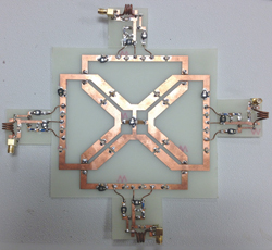
Figure 5 The four-element transceiver array with matching boards.
Hardware Implementation and Experiment Results
The transceiver array was fabricated on a 1/32" FR-4 printed circuit board (PCB) with 1 oz copper (see Figure 5). The capacitance in simulations was directly applied for tuning and decoupling. Readjustment that follows the same procedure as in simulations was required. It was found that the actual capacitance differed from simulation results by 10 to 20 percent. Since the bought capacitors have a 10 percent tolerance, this agreement was considered to be very good.

Figure 6 Measured |S11| of one coil when other coils are terminated with a 50 Ω load.

Figure 7 The complete transceiver array with power dividers and baluns.
Each coil was matched to 50 Ω by a standard highpass L-network. Figure 6 shows the measured S11 of one coil when all other coils were matched to a 50 Ω load. In this measurement, a bucket of saline water that mimics the loading of the human body was applied. A sharp resonant curve (<-30 dB) was observed, which indicates that good matching and decoupling were achieved at the same time. Baluns made of wound semi-rigid coaxial cables were connected to each coil to choke unwanted shield currents.10 Each coil was then connected to a T/R switch tuned with an insertion loss between 0.2 and 0.3 dB and an isolation less than –40 dB.10

Figure 8 MR image of a bucket of saline water.
On the transmit side, three Wilkinson power dividers were constructed to split a single RF input from the scanner equally four ways. Appropriate phases were implemented by phase shifters according to Table 1. Four receiver channels were connected to an interface box custom made by Stark Contrast Inc., Erlangen, Germany. Finally, the interface box was connected directly to a Siemens’ 3T scanner. The complete transceiver array is shown in Figure 7.
MR images were acquired with gradient echo sequence on the 3T scanner. The acquisition matrix size was 280 × 280, slice thickness = 8 mm, TE = 3.68 ms and TR = 10 ms. In the first experiment, the same bucket of water used in bench measurement was imaged. The result is shown in Figure 8. As can be seen, a bright region appears underneath each coil due to the fact that image intensity is strongly modulated by receiver sensitivity profile. However, at the depth where the heart should be, peak image intensity locates near the symmetry axis. Thus aligning the geometry center of the coil with the heart should yield optimal image quality. This was confirmed in the second imaging experiment, in which the transceiver array was tested on the first author. As shown in Figure 9, the image intensity in the heart is the strongest.
Conclusion

Figure 9 Actual image of a subject's heart.
A complete design workflow for a four-channel transceiver array is detailed in this article. By employing a four-element clover layout, sufficient mutual decoupling and good transmit field coverage were achieved at the same time. Experimental results show that with careful hardware implementation, satisfactory signal intensity can be acquired in the heart.
References
- D. Hoult and C.N. Chen, Biomedical Magnetic Resonance Technology, Taylor & Francis: Oxford, UK, 1989.
- T.O. Woods, “Standards for Medical Devices in MRI: Present and Future,” Journal of Magnetic Resonance Imaging, Vol. 26, No. 5, November 2007, pp. 1186-1189.
- K. Ugurbil et al., “Ultrahigh Field Magnetic Resonance Imaging and Spectroscopy,” Journal of Magnetic Resonance Imaging, Vol. 21, No. 10, December 2003, pp. 1263–1281.
- P.F. Van de Moortele et al., “B1 Destructive Interferences and Spatial Phase Patterns at 7 T with a Head Transceiver Array Coil,” Magnetic Resonance in Medicine, Vol. 54, 2005, pp. 1503–1518.
- P.B. Roemer et al., “The NMR Phased Array,” Magnetic Resonance in Medicine, Vol. 16, No. 2, November 1990, pp. 196–225.
- K.P. Pruessmann et al., “SENSE: Sensitivity Encoding for Fast MRI,” Magnetic Resonance in Medicine, Vol. 42, 1999, pp. 952–962.
- D. Spencer et al., “Design of a 32 Channel Cardiac Array for Parallel Imaging,” Proceedings of the 2005 International Society for Magnetic Resonance in Medicine.
- FEKO Suite 6.1, EM Software and Systems (www.feko.info), 2011.
- E.M. Hackee et al., Magnetic Resonance Imaging: Physical Principles and Sequence Design, John Wiley & Sons: New York, NY, 1999.
- X. Yang et al., “T/R Switches, Baluns, Traps and Active Detuning Elements,” Proceedings of the 2006 International Society for Magnetic Resonance in Medicine