 | |||
Once again the global market for capable electronic intelligence gathering systems is heating up in the wake of increased investments supporting homeland defense both in the US and overseas. Companies that already develop and produce microwave receivers capable of covering the UHF thorough millimeter-wave bands may already have products suitable to address these emerging markets. The intelligence community demands systems that can capture, identify, characterize and record radar pulses over wide operating frequency ranges and in extremely dense pulse environments.
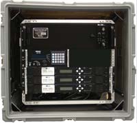
The SenSyTech Pulse Analyzer Unit (PAU) functions as the heart of an electronic intelligence (ELINT) system. Receiving inputs from microwave receivers and demodulators, the PAU analyzes the signals from these receivers and delivers the output to an operator’s display. A typical ELINT system is shown in Figure 1. The PAU supports the collection and display of two basic types of data — pulse descriptor words (PDW) and intra-pulse descriptor words (IDW). These data types are produced in support of data collection and analysis operations. Optionally, the PAU can also digitize the IF output of tuners and provide the result to analysis displays and external equipment.
 | ||
| Fig. 1 Typical ELINT system. | ||
While the PAU shown in the figure accepts detected log video and FM video from four receivers, the number of receivers is customer defined. Note also that the receivers shown have imbedded demodulators that produce these output signals. Alternatively, if the selected receivers only produced IF signals, demodulators could be provided as external components to derive the full system capability.
The PAU can also be provided as a stand-alone product to interface with existing tuners and antenna systems. In this case, the PAU can interface with most microwave tuners available on the market as well as control existing antenna systems having interfaces conforming to a commercial standard.
Pulse Analyzer Unit Description
The PAU consists of two VME circuit card assemblies — a real time processor and a pulse digitizer assembly. A block diagram of the PAU is shown in Figure 2. The real time processor is a dual power PC running on a Linux operating system. It communicates with the pulse digitizer over the VME bus and generates an operator interface with a display and keyboard plus trackball or mouse. The pulse digitizer assembly employs several A/D converters and FPGA cores to act on the digitized data. Ample memory resources store the information for subsequent analysis and display. The PAU is expandable to accommodate additional tuners by inserting additional pulse digitizer assemblies. When acting on log and FM video, each digitizer assembly can interface with up to four tuners. These boards are packaged in a VME enclosure along with standard peripherals (hard disk, CD, etc.) to make up the PAU.
 | ||
| Fig. 2 Pulse analyzer block diagram. | ||
The PAU supports the following capabilities:
- Configuration/Built-in Test (BIT)
- Automatic Search and Acquisition/DF
- Sparkle Display and Collection Control
- PDW Analysis
- IDW Analysis
- Real Time Raster
- IFS Analysis/Recording and Playback (when connected to an IF source).
Configuration/Built-in Test
The Configuration/Built-in Test (BIT) function allows a user to set up a system to define the resources available. The user can enter both the number of PAUs in the system and the number of tuners connected to each PAU, and describe the capabilities of the tuners. In addition, certain system alignment functions are performed to establish signal timing between tuner outputs. This mode also facilitates the creation of threshold tables to be used in the pulse detection process. This function also reports BIT results for the PAU, and any attached tuners and other system components.
Automatic Search and Acquisition/DF
The PAU supports both automatic and manual modes of operation. Search and acquisition/DF is an automatic mode whereby the system searches for emitters within frequency ranges of interest, and lists these in a summary display for review. The operator can select one or several start/stop frequency ranges, and the number of tuners to be assigned to the search/acquisition function. The allocated tuners are step tuned over the frequency range while the PAU looks for signal activity. When activity is found, pulses are collected and deinterleaved in order to extract the parameters of the signal. Signal parameters are displayed in summary format, and details of the parameters can be obtained by opening up a detail panel for any selected emitter. After characterizing the signal, the tuner is returned to its step/dwell function to continue searching the defined frequency range.
The deinterleaver used by the PAU to summarize pulse activity is a SenSyTech software item that enjoys over a decade of use in the field. The algorithms generically process pulse data to derive pulse train parameters, and will compare those parameters to an on-line library to identify the radar type. The PAU supports the detection and processing of both frequency and pulse rate interval (PRI) agile radar signals. Types of frequency modulation supported include CW, constant, frequency modulation on pulse (FMOP) and agile (pulse-to-pulse, and switch and dwell). Types of PRI modulation supported include CW, constant, jittered, discrete jittered, staggered, pulse modulation, and switch and dwell. If the system is configured with a directional antenna, and direction is selected as a parameter of interest, then angle-of-arrival will be measured for each intercepted emitter and displayed.
Sparkle Display and Collection Control
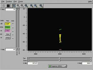
The sparkle display, shown in Figure 3, helps an operator find and isolate signals of interest from other background signals. It provides a visualization of emitter/pulse activity within the tuner’s bandwidth. The display provides controls to manipulate the tuner’s center frequency and bandwidth in order to tune to the desired frequency and frequency range of interest. Also provided on the display are qualification criteria that assist the operator in isolating signals of interest by such parameters as amplitude, pulse width and frequency. Once the signal is isolated, the operator may collect a selected number of PDWs or IDWs. Status of the collection is provided visually so the operator knows how many of the requested PDWs or IDWs have been collected. Once complete (or terminated by the operator) the data may be saved to disk and/or inspected with the PDW or IDW analysis displays.
 | ||
| Fig. 3 Sparkle display. | ||
PDW Analysis
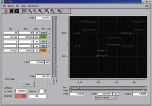
The PDW analysis function reads PDWs that have been stored on disk or in memory and provides an X-Y plot to support detailed analysis. The plot allows an operator to view any PDW parameter or combination of parameters on the Y-axis, and plots any one PDW parameter on the X-axis. Figure 4 shows an example of the display with amplitude, pulse width, frequency, TOA and DTOA enabled on the Y-axis, plotted against TOA on the X-axis.
 | ||
| Fig. 4 PDW analysis display. | ||
Each of the parameters on the Y-axis has an independent scale that can be zoomed and unzoomed through the use of cursers, or can be manipulated manually by typing in the minimum and maximum ranges for the selected scale. The same is true for the X-axis. Placing vertical cursers on either side of data of interest and hitting the “zoom” feature will rescale the display to show higher resolution for data of interest.
PDWs of particular interest can be selected by drawing a square around the data, and saving the PDWs to a file. Alternately, PDWs that are not of interest can be deleted by drawing a box around the data and erasing the contents of the box. Modified PDW data can be resaved to the original file or to a new file name. In addition, saved PDW files can be overlaid with one another to inspect slight deviations in pulse train parameters.
IDW Analysis
The IDW analysis display provides the means to analyze intra-pulse samples of selected signals. Pulses that match collection criteria are digitized at a maximum rate of 100 MHz. Time, amplitude and frequency parameters are stored for each sample. The IDW analysis display presents this information for individual pulses, or allows multiple pulses to be seen together for comparison purposes. The display allows frequency modulation on pulse (FMOP), pulse width modulation (PWM) and amplitude modulation (AM) patterns to be seen and measured. In addition, if the pulses exhibit phase modulation on pulse (PMOP), the phase transitions can be seen within the FMOP analysis window.
Real Time Raster
The Real Time Raster (RTR) display, shown in Figure 5, provides a falling raster presentation of pulse activity, and allows operator interaction to precisely interrogate the PRI characteristics of the captured pulses. Unlike the PDW or IDW analysis displays, the RTR is a real time function that presents live data as it is digitized. Detected pulses are shown on a scrolling vertical axis that represents “coarse” time. The horizontal axis represents “fine” time, and can be adjusted in large and small increments to line up the pulse data into an indicative PRI train. A viewing panel can be configured to display other pulse parameters to inspect other aspects of the pulse trains.
 | ||
| Fig. 5 RTR display. | ||
IFS Analysis/Recording and Playback
This capability is a future growth capability where it is envisioned to provide detailed phase, frequency and time analysis of data extracted from a digitized IF. Current A/D speeds allow analysis over a 20 MHz bandwidth from an IF provided at 70 MHz, or optionally at baseband. Recent advancements in commercial off-the-shelf digital component technology, to include integrated FPGA/microprocessor technology were major contributors to the development of this ELINT processing solution with size/performance/cost tradeoffs previously unattainable.
SenSyTech Inc.,
Newington, VA
(703) 550-7000, www.sensytech.com.
