Scientific investigation in the upper millimeter-wave region has long been accomplished using equipment built by the researcher for his specific task. The signal sources used were multipliers driven by either Gunn diode oscillators or backward wave oscillators that were available up through 110 GHz. Signal detection was done with special built narrow band detectors or harmonic mixers. Researchers were often hampered in their investigation due to the narrow band nature of the test equipment.
The most common investigations in the millimeter-wave frequency range are spectral line investigation, molecular particle signature identification and material property characterization. Because of atmosphere effects on millimeter-wave transmission, emerging millimeter-wave applications include communications, transportation, scientific research and homeland security.
Full waveguide bandwidth vector network analysis (VNA) systems capable of measuring absorption, reflectivity and scattering properties through 110 GHz were available in the early 1980s. In the late 1990s, the full waveguide bandwidth capability had gone up to 220 GHz. By 2002, a 220 to 325 GHz vector network analysis system was available. As the 325 GHz waveguide VNA system became available, researchers began to demand higher waveguide frequency bands. It is this demand that drove the 500 GHz and above frequency extension module development.
The development of the 325 to 500 GHz VNA frequency extension modules presented here represents the highest frequency possible where sub-harmonic contamination suppression can be achieved while using 20 GHz synthesizers. Using practical multiplier schemes to reach the next band above 500 GHz is impacted by the sub-harmonic contamination inside the bandpass of the waveguide to the degree that it is not filterable.
The WR-02.2 Frequency Extension Module Architecture

Figure 1 depicts the WR-02.2 frequency extension module architecture. This architecture is in alignment with using the 20 GHz synthesizer for the LO and RF input — above 20 GHz the synthesizer uses a ×2 and/or ×3 multiplier to extend the synthesizer frequency coverage with phase noise degradation at 20log(n), offering no advantages over the integrated multipler/amplifier in the millimeter-wave frequency extension module.
The RF input frequency is amplified and multiplied to a total multiplication factor of 30 to reach the 325 to 500 GHz frequency range. An input isolator is added to the RF doubler/amplifier input to diminish amplitude fluctuation from the RF cable and connection interface mismatch. The doubler/amplifier output signal drives the ×15 multiplier chain to produce the output frequency at the WR-02.2 frequency band. The ×15 multiplier chain, selected during the initial design stage, optimizes for the least in-band sub-harmonic contamination with realizable filtering. A lower RF multiplication factor multiplier chain, using a combination of ×2 or ×3, would avoid much in-band sub-harmonic contamination but this would require inter-stage amplification. An amplifier at W-band or higher is commercially scarce and not without its own problems; furthermore, the complicity of the multiplier chain would increase. This ×15 multiplier chain achieves an average –32 dBm output power as measured with a calorimeter.
The LO input frequency is amplified and multiplied to a net multiplication factor of four before the millimeter-wave harmonic mixer LO input. An input isolator is located at the LO doubler/amplifier input to mitigate amplitude fluctuation due to LO cable and interface mismatch. The doubler/amplifier output signal is split equally to drive the next doubler chain that energizes the LO port of the millimeter-wave reference and test harmonic mixer. To optimize the match between the splitter and the doubler, an isolator is placed at the doubler input port. The doubler generates +10 dBm minimum output power at the WR-15 frequency band, more than sufficient RF power to properly bias the millimeter-wave harmonic mixer. The simplicity of this LO chain topology has proven in the lower millimeter-wave frequency bands that the inherent LO phase coherence offers the optimal high level noise performance response.

The 325 to 500 GHz frequencies are coupled through a 10 dB coupler to the millimeter-wave harmonic mixer RF input. The millimeter-wave harmonic mixer IF output has been optimized for the output frequency range of 5 to 300 MHz. A > 50 dB gain multi-stage IF amplifier boosts the peak IF output to –13 dBm. –13 dBm power output is selected to prevent saturation to the vector network analyzer internal IF chain and simultaneously maximizes the vector network analysis system dynamic range. Depending on the millimeter-wave vector network analysis system used, the –13 dBm IF output power may have to be reduced to prevent saturation to the millimeter test set controller.
Millimeter-Wave Component Design

The WR-02.2 component design can be divided into two challenging areas: 3D EM analysis with devices embedded in and out of the waveguide structure and machining realization of those millimeter-wave components. The challenges in designing millimeter-wave multipliers (see Figure 2) and mixers (see Figure 3) using commercial software packages such as HFSS from Ansoft and Agilent have been the absence of good, accurate model simulations to seamlessly simulate designs with devices and circuit embedded inside the waveguide and circuits outside of the waveguide. Henceforth, multiplier and mixer design becomes a piecemeal design encompassing simulations, assumptions, experience and a lot of experimentations. Electromagnetic-field simulation establishes the baseline for the best planar circuit material (softboard or ceramic) to be used in the waveguide frequency band of interest and provides detailed analysis of passive circuits outside of the waveguide channel. Passive components such as a coupler, with performance strongly tied to mechanical dimensions, has had good correlation between simulation and measured results. The WR-02.2 10 dB coupler was analyzed intensively with HFSS.

The next challenge is to be able to realize those millimeter-wave components through precision machining. Surface finish and mechanical interface are critical due to the small size of the wavelength in this frequency band. The best commercially available milling machine is taxed to the limit to produce the surface finish and mechanical tolerance required for the WR-02.2 components.
T-6061 aluminum was chosen for the WR-02.2 dual directional coupler because of its low thermal expansion properties and ease of machining. The waveguide channels are 0.022 × 0.011 inches and any growth in the dimensions of the waveguide or its length due to temperature change can potentially destroy the efficacy of a calibration. Tooling to produce this coupler with the proper surface finish and accuracy requires extremely small endmills with spindle speeds in excess of 12,000 rpm. Because of the coupler’s intricacy and the finishing quality, machinist skill becomes one of the most important aspects in manufacturing this component.

Results and Discussion
Figure 4 shows a typical WR-02.2 multiplier chain output power. A calorimeter is used in measuring the WR-02.2 output power. A 310 GHz high pass filter is inserted at the WR-02.2 multiplier chain output to suppress sub-harmonic power contribution. The sub-harmonic power contamination is the result of the high harmonic number multiplier used. Design work to improve output power and to alleviate the sub-harmonic contamination problem is ongoing. A stand-alone mixer test system at these frequencies is not available. Therefore, mixers are tuned and optimized in the WR-02.2 frequency extension module.

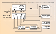
Figure 5 shows the complete WR-02.2 “two-port” VNA measurement system. The data taken uses the Agilent 8510/85105A millimeter-wave vector network analyzer system due to its availability at the time of the test and the good phase noise characteristic of the 8362x synthesizers. However, a millimeter-wave vector network analyzer system such as the Agilent PNA/N5260A with two external low phase noise option synthesizers or the Anritsu ME7808, 37347D/3738A can be used with the WR-02.2 frequency extension modules. The millimeter module configuration equation is set for an RF frequency multiplication factor of 30, an LO frequency multiplication of 28, an IF frequency range of 20 MHz and a sweep frequency range between 325 to 500 GHz.
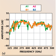
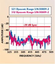
Figure 6 depicts the reference and test port mixer raw response of two different WR-02.2 frequency extension modules. Ignoring the few discrepant points, the overall reference and test mixer raw responses track each other closely across the frequency band. Moreover, the vector network analysis system is able to discern the RF path sub-harmonic contamination — indicating a good calibration is attainable. The system dynamic range plot, depicted in Figure 7, exemplifies an outstanding achievement for this frequency range. With new filtering hardware in the RF path, it is anticipated that the raw mixer responses may be smoother across the frequency band and possibly improve the overall system dynamic range.

Conclusion
A viable and compact WR-02.2 millimeter-wave frequency extension transmission/reflection module for use with a vector network analyzer has been described. The WR-02.2 module extends the microwave vector network analyzer two-port S-parameter measurement capabilities to the 500 GHz frequency range. More importantly, the WR-02.2 T/R modules are “plug & play” when used in a millimeter-wave vector network analysis system such as Agilent’s PNA/N5260A, 8510/85105A and Anritsu’s ME7808, 37347D/ 3738A. Planned improvements to the WR-02.2 frequency extension module will allow the module to test active devices without restrictions.
Note: This material was presented at the 66th ARFTG Conference in Washington, DC in December 2005 and published by ARFTG at that time.
OML Inc.,
Morgan Hill, CA (408) 779-2698,
www.omlinc.com.
