For the effective use of the available frequency spectrums, the channels of conventional communications satellite systems are allocated contiguously in frequency. Each channel is filtered by a channel filter with high frequency selectivity, amplified by a high power amplifier and transmitted to the ground through a single beam. Modern satellite systems often use a complex arrangement of frequency plans and spatial coverage. Such systems may require compact filters with multiple passbands.
Microwave filters for satellite applications generally require the lowest mass possible because of the high launch cost of the payload. Therefore, the techniques of dual-mode elliptic response filters have long been considered to reduce the size and mass for satellite applications.1 Due to their ease of fabrication and tuning, the in-line type, dual-mode filters, with input and output ports positioned on opposite sides of the structure, have been widely used for satellite applications.2–4 Holme has realized an in-line type, dual-mode, dual-passband filter with an elliptic response by allowing transmission zeros to be used to separate the filter into multiple passbands.5 However, the N-pole, in-line type, dual-mode filter can realize N/2 transmission zeros at the most. Therefore, implementation techniques for the dual-passband filter with a canonical structure are required to increase the number of zeros up to N-2.6
This article presents the implementation techniques of a dual-passband filter with an asymmetric canonical structure. An asymmetric canonical structure is chosen not only to increase the transmission zeros of dual-passband filters, but also to get high isolation between input and output coupling elements. Very effective nonlinear equations are extracted to obtain the coefficients of the transfer function from the coupling matrix for synthesizing the six-pole filter with an asymmetric canonical structure. The configuration of the equivalent circuit with lumped elements is proposed and the lumped element values are obtained. To validate the proposed implementation approach, a six-pole, dual-mode, dual-passband filter for satellite applications was fabricated. Very good agreement between the measured and computed responses is obtained.
Dual-passband Filter Transfer Function
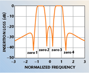
For the single-passband elliptic function filter with high frequency selectivity, all poles are located within the passband and all the zeros are located out-of-band. However, for a dual-passband realization, zeros may be used to split the single passband into two passbands, as shown in Figure 1. Furthermore, two zeros between each passband are indispensable for realizing a dual-passband by splitting a single-passband. The dual-passband, elliptic function filter with high frequency selectivity should therefore be of a configuration that can realize at least four zeros. Generally, N-2 zeros for the N-pole resonator filter are located on the complex frequency(s) if the coupling value between the first and last resonator is non-zero. Poles and zeros are determined after optimization for the desired dual-passband filter response. From the optimized poles and zeros to meet the stringent specification, the transfer function of a symmetrical six-pole filter with four zeros is written with respect to s as

where
? = ripple factor
In this article, the coefficients of the denominator and numerator polynomials and the ripple factor for the design of a dual-passband filter with better than 22 dB return loss in the passband are chosen as az2 = 1.9531, az0 = 0.1182, ap5 = 1.0961, ap4 = 2.5333, ap3 = 1.6303, ap2 = 1.6228, ap1 = 0.4296, ap0 = 0.2144 and ? = 5.1370, respectively.
Six-pole Filter Coupling Matrix

Due to their ease of fabrication and tuning, the in-line type, dual-mode filters, with the input and output ports positioned on opposite sides of the structure, have been designed widely for satellite applications.3,4 However, the N-pole, in-line type, dual-mode filter can realize N/2 transmission zeros at the most. It is possible to increase the number of zeros up to N-2 by employing a canonical structure.5 Figure 2 shows the signal flow diagrams for six-pole symmetric and asymmetric canonical filters. Since the coupling matrix of a symmetric canonical filter is symmetric (M12 = M56 and M23 = M45), for most practical cases it can be obtained easily. However, the symmetric canonical filter has a major drawback when it is realized with the dual-mode technique. There is an isolation problem due to the fact that the input and output coupling elements are in the same physical cavity. Therefore, the asymmetric canonical filter is an alternative structure to solve this problem.7 For an N-pole, lossless resonator filter, the transmission coefficient S21 is given as8
![]()
where
RT = input/output-termination resistance
Here [A] is a N-square matrix containing the complex frequency variable s and the frequency-independent couppling coefficients Mpq

The transmission coefficient (Equation 2) for an N-pole filter can be described as a fractional expression like the transfer function with the denominator and numerator polynomials. The denominator polynomial of Equation 2 is equal to the determinant of [A] with respect to s. The numerator of the transmission coefficient can be obtained from the determinant of the matrix in which the elements of the Nth row and the 1st column are removed. The synthesis method of a four-pole filter with two zeros was proposed by solving the nonlinear equations of the relation between the coefficients of the transfer function and the coupling matrix.9 This method is very useful for a four-pole filter, but any other equations were not provided for an arbitrary structure. By using the well-known algorithm10 for the computation of the determinant, very effective equations can be derived to obtain the coefficients of the denominator polynomial and the numerator polynomial with respect to s from the coupling matrix and the termination resistance for a six-pole filter with an asymmetric canonical structure. These equations for each coefficient are given as


The coefficients of the denominator polynomials and the numerator polynomials given by Equation 4 should be equal to the coefficients of the polynomials given by Equation 1. Thus, the goal function, obtained by comparing the coefficients of polynomials, is expressed for optimization as

The gradient optimization method, with the goal function presented in this article, is applied to the filter using commercial mathematical tools such as MathCAD.™ The coupling values obtained by optimization are shown in Equation 6. Note that the coupling matrix has alternating larger and smaller adjacent resonator couplings.11 Figure 3 shows the frequency response of the transfer function (Equation 1) and coupling matrix ([M]) given by Equation 6. Note that the response of the transfer function and that of the coupling matrix cannot be distinguished. This agreement verifies the presented synthesis method for the presented topology of the resonator filter

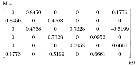

RT = 0.5480
Six-pole Filter Equivalent Circuit Model
For satellite communication systems that have stringent requirements for low insertion loss and high power capacity, it is usually necessary to implement the filters in waveguide. As shown in Figure 4, a six-pole, dual-passband filter with an asymmetric canonical structure consists of dual-mode, circular waveguide cavities excited in their TE113 mode, coupling irises and tuning screws. In each cavity, a screw at a 45° angle from the polarization axes couples the dual modes and tuning screws adjust the resonant frequencies.

In order to design this filter, an appropriate electrical model of the filter network is needed with frequency-dependant impedance inverters. An electrical model with the same filter configuration is especially practical to estimate the length of each cavity. Input and inter-cavity irises act as shunt inductive discontinuities whose magnitudes are determined by the length of slots. The output iris and the coupling screws can be replaced with capacitors, as shown in the equivalent circuit. In this model, ideal normalized transmission lines (1?) are used for resonators as a matter of convenience. A length of three or four half-wavelengths for the cavity is usually chosen to obtain higher unloaded Qs (Qu) and practical coupling coefficients. In this article, three half-wavelength long cavities are chosen. Since the method to determine the lumped element values is already well described in the literature,12,13 it is not repeated here. When the center frequency of the filter is 21 GHz, with 150 MHz of bandwidth, the final results for the element values and the electrical lengths of the cavities are given in Tables 1 and 2. As shown, the electrical length of each cavity has different phases due to the adjacent lumped elements. Figure 5 shows the frequency response of the six-pole filter with an asymmetric canonical structure. The simulated results, using the equivalent circuit model with the lumped element values given in the table, have shown good agreement with results from the ideal impedance inverter.

Fabricated Six-pole, Dual-band Filter
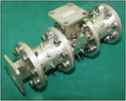
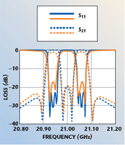
The filter is realized using iris coupled cylindrical waveguide cavities operating in the TE113 orthogonal degenerate modes for volume and mass reduction. The diameter of the cavities is carefully selected to control the higher order modes and to optimize the Qu, which influences the in-band performances and the losses. In order to determine the length of the cavities, both the electrical lengths given in the table and the added length from the finite iris thickness have to be considered. The filter consists of three circular cavities with small length variations over the temperature range. Each open ended cylindrical cavity was machined from solid Invar 36, a low thermal expansion alloy, which provides a stable RF performance over the specified temperature range. The irises are made from a thin sheet of Invar 36. As shown in Figure 6, the cavities, irises and tuning screws are finished with silver-plating to minimize the insertion losses. Before assembling the filter, the sizes of the input/output and inter-cavity slots must be chosen by measuring the inter-cavity couplings.14 After the slots are set, the tuning screws and coupling screws must be adjusted. The filter is divided into two short-circuited pieces and screws are adjusted by measuring the phase response of the input reflection coefficient. Figure 7 shows the computed and measured responses of the filter. The measured results of the experimental filter show good agreement with the theory. The presented filter structure and design techniques can be applied not only to satellite communications systems but also to commercial communications systems.
Conclusion
This article presents the implementation techniques for a Ka-band, dual-passband filter with an asymmetric canonical structure. An asymmetric canonical structure is chosen, not only to increase the transmission zeros of dual-passband filters, but also to get high isolation between input and output coupling elements. Very effective nonlinear equations to obtain the coefficients of a transfer function from the coupling matrix values have been proposed for synthesizing the filter. The configuration of the equivalent circuit with lumped elements has been proposed and the values of lumped elements have been obtained. To validate the proposed implementation approach, a six-pole, dual-mode, dual-passband filter for satellite applications has been fabricated. Very good agreement between the measured and computed responses has been obtained. The presented filter structure and design techniques can be applied not only to satellite communications systems but also to commercial communications systems.
References
1. A.E. Williams, “A Four-cavity Elliptic Waveguide Filter,” IEEE Transactions on Microwave Theory and Techniques, Vol. 18, No. 12, December 1970, pp. 1109–1114.
2. J.R. Montejo-Garai and J. Zapata, “Full-wave Design and Realization of Multi-coupled Dual-mode Circular Waveguide Filters,” IEEE Transactions on Microwave Theory and Techniques, Vol. 43, No. 6, June 1995, pp. 1290–1297.
3. J. Lee, M.S. Uhm, I.B. Yom, S.P. Lee and C.K. Choi, “Simultaneous Reduction of Amplitude and Group-delay Variation of Input Demultiplexer for Ku-band Satellite Transponder,” 2003 IEEE Vehicular Technology Conference Digest, pp. 2669–2672.
4. S. Kahng, M.S. Uhm and S.P. Lee, “A Dual-mode Narrow-band Channel Filter and Group-delay Equalizer for a Ka-Band Satellite Transponder,” ETRI Journal, Vol. 25, No. 5, October 2003, pp. 379–386.
5. S. Holme, “Multiple Passband Filters for Satellite Applications,” 20th AIAA International Communications Satellite Systems Conference & Exhibit, paper no. AIAA-2002–1993, 2002.

Man Seok Uhm
6. A.E. Williams and A.E. Atia, “Dual-mode Canonical Waveguide Filters,” IEEE Transactions on Microwave Theory and Techniques, Vol. 25, No. 12, December 1977, pp. 1021–1026.
7. R.J. Cameron and J.D. Rhodes, “Asymmetric Realizations for Dual-mode Bandpass Filters,” 1980 IEEE MTT-S International Microwave Symposium Digest, pp. 138–140.
8. S. Amari, “Synthesis of Cross-coupled Resonator Filters Using an Analytical Gradient-based Optimization Technique,” IEEE Transactions on Microwave Theory and Techniques, Vol. 48, No. 9, September 2000, pp. 1559–1564.
9. A.E. Williams, “A Four-cavity Elliptic Waveguide Filter,” IEEE Transactions on Microwave Theory and Techniques, Vol. 19, No. 12, December 1970, pp. 1109–1114.
10. F. Ayres, Jr., Schaum’s Outline Series: Theory and Problems of Matrices, SI Edition, McGraw-Hill Inc., Singapore, 1974.
11. D.R. Jachowski, “Folded Multiple Bandpass Filter with Various Couplings,” US patent 5410284, April 25, 1995.

In Bok Yom
12. J.S. Hong and M.J. Lancaster, Microstrip Filters for RF/Microwave Application, John Wiley & Sons Inc., Hoboken, NJ, 2001.
13. K.L. Wu, “An Optimal Circular-waveguide Dual-mode Filter Without Tuning,” IEEE Transactions on Microwave Theory and Techniques, Vol. 47, No. 3, March 1999, pp. 271–276.
14. A.E. Atia and A.E. Williams, “Measurements of Inter-cavity Couplings,” IEEE Transactions on Microwave Theory and Techniques, Vol. 23, No. 6, June 1975, pp. 519–522.
Man Seok Uhm received his BE and ME degrees in electronic communications engineering from Chungang University, Seoul, South Korea, in 1987 and 1989, respectively. He joined the Electronics and Telecommunications Research Institute (ETRI), Daejeon, South Korea, in 1992, and has since developed experimental transponder systems, antennas, and engineering qualification model active and passive components in the satellite communications department. His current research interests include microwave active and passive components, satellite antennas, satellite transponders and electromagnetic field theory.

Juseop Lee
In Bok Yom received his BS and MS degrees in electronic communications from Hanyang and Chungnam National Universities, South Korea, in 1990 and 2004, respectively. He joined the Electronics and Telecommunications Research Institute (ETRI) in 1990, and has since developed transponder systems, engineering qualification model active and passive components in the satellite communications department. He is currently the chief of the satellite communications RF techniques team at ETRI, Daejeon, South Korea. His research interests include microwave active and passive components, satellite transponders and electromagnetic field theory.
Juseop Lee received his BS and MS degrees in radio science and engineering from Korea University, Seoul, South Korea, in 1997 and 1999, respectively. From 1999 to 2001, he was a research engineer with LG Electronics, Gumi, South Korea, where he was involved in reliability and performance analysis of RF components for CDMA systems. From 2001 to 2005, he was with the Electronics and Telecommunications Research Institute (ETRI), Daejeon, South Korea, where he was a researcher responsible for the development of passive RF equipment for Ku- and Ka-band communications satellites. In September 2005, he joined the electrical and computer science department of the University of Michigan, Ann Arbor, MI, where he is currently working toward his PhD degree. His research interests include RF and microwave components, satellite transponders and electromagnetic theory.

Jeong Phill Kim
Jeong Phill Kim received his BS degree in electronic engineering from Seoul National University, Seoul, South Korea, in 1988, and his MS and PhD degrees in electronic engineering from Pohang University of Science and Technology, Pohang, South Korea, in 1990 and 1998, respectively. From 1990 to 2001, he was a research engineer in the R&D center at LG Innotek, where he was involved with the design of antennas, transmitters and receivers for various radar systems. Since 2001, he has been a faculty member in the school of electrical and electronic engineering, Chung-Ang University, Seoul, South Korea. His current research interests include the design of antennas, RF and microwave components, on-chip tunable filters RFID systems applications and various communication applications of true random signals.
