Commercial communications satellite operators face a difficult problem. In the rapidly evolving global telecommunications industry, entire market segments can emerge, thrive, change and disappear during the fifteen-year on-orbit lifetime of a modern communications satellite. To address these changing market needs, it would be desirable to have a communications payload that could reconfigure its antenna beam patterns after the spacecraft is placed on orbit. This capability would have the added benefit of allowing the satellite operators to use a single satellite design for multiple orbital slots, simplifying sparing and reducing the operators’ overall satellite acquisition cost. This on-orbit flexibility, however, must be achieved within the stringent constraints of size, mass, cost, power consumption, reliability and technical risk that are required for commercial communications satellite payloads.
Current US military communications satellites have the ability to reconfigure their antenna patterns on orbit. The Defense Satellite Communications System III (DSCS III) satellites transmit and receive through SHF multiple beam antennas (MBA) with programmable beam forming networks (BFN). The programmable BFNs are used to re-shape the spacecraft’s antenna patterns as needed under ground control. The MILSTAR II spacecraft has autonomous anti-jam nulling antennas on the uplink of its Medium Data Rate payload. These multiple beam antennas use programmable BFNs to automatically re-shape the spacecraft’s antenna patterns whenever an uplink jammer is detected. The next generation of Advanced EHF satellites, currently under construction, also have an adaptive uplink nulling capability.
In many regimes of coverage and gain, MBAs with programmable BFNs are superior to active phased arrays in terms of cost and power consumption. They offer lower development risk due to their long spaceflight heritage (the first DSCS III BFNs were launched in 1982). MBAs with programmable BFNs are therefore an attractive alternative for providing on-orbit reconfigurability for next-generation commercial communications satellites. They provide the required performance and flexibility within the tight cost and schedule constraints of commercial space programs.
Multiple Beam Antennas vs. Phased Arrays for Earth Coverage from Geostationary Earth Orbit (GEO)
Multiple beam antennas are defined1 as antennas with multiple input (or output) ports such that different radiation patterns are obtained when signals are impressed on the different ports. In most practical implementations a pencil beam results when a signal is applied to a single input. Different inputs map to pencil beams pointing in different directions. The term MBA is generally reserved for antennas with more than five ports to exclude monopulse and four-horn sequential lobing antennas from the category.
Probably the most widely employed MBA is the reflector illuminated by an array of multiple feed horns, as shown in Figure 1. Other examples are lens antennas fed by multi-horn arrays, as shown in Figure 2, and planar arrays fed by Butler matrices or Rotman lenses.

Fig. 1 A Cassegrain reflector antenna fed by an array of horns.
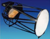
Fig. 2 A 265-port switched-beam lens antenna featuring adaptive nulling on any contiguous seven-horn cluster.
The N beams that are produced by exciting each antenna port in turn define the field of view of the MBA. These beams, referred to as the component beams of the antenna, form a linear basis of the set of antenna patterns that can be realized with the MBA. The beam forming network (BFN) connects to the N ports of the MBA and provides excitations of the correct amplitudes and phases at all ports to produce the desired antenna pattern.
In a phased array antenna, on the other hand, each “port” of the antenna is a radiating element that produces a radiation pattern covering the entire field of view of the antenna. The antenna patterns produced by each radiating element are identical to a good approximation. The desired composite antenna pattern is achieved by choosing the amplitude and phase of the excitation of each radiating element such that they interfere in the far field to produce a beam of the desired shape and pointing angle within the antenna’s field of view.
The key design parameters for an MBA are the minimum antenna gain required over a coverage area and the angular size of the coverage area as seen from the spacecraft. The minimum required antenna gain must be equal to the peak gain of the component beams minus the worst-case cross-over gain level between adjacent beams. If multiple beams must be turned on simultaneously then a weighting factor for the multiple beams must also be included.
The minimum required antenna gain and the choice of the cross-over gain level together determine the size of the antenna’s aperture. Higher gain levels require larger apertures (either lens or reflector). The angular size of the coverage area then determines the number of individual feed elements (and thus the number of ports on the BFN) that are required for the coverage area.
For the phased array, the minimum gain requirement also determines the size of the radiating aperture. In the case of the phased array, this radiating aperture is not a reflector or lens; it is an area populated with individual direct radiating elements such as horn or patch antennas. The total number of these elements, and thus the cost and complexity of the phased array, is driven by the inter-element spacing used within the radiating aperture. This inter-element spacing is in turn driven by the angular area over which grating lobes must be suppressed in the field of view of the antenna. Grating lobes are spurious antenna beams that result from large inter-element spacings in the aperture. The grating lobes can have gains comparable to the main lobe of the antenna. They are analogous to aliasing responses in digital signal processing when a signal is under-sampled. To completely eliminate grating lobes in the field of view of a phased array, the minimum distance between neighboring radiating elements along any plane cutting the array face must be less than the shortest operating wavelength of the antenna. A common method of achieving this is to place the radiating elements on a rectangular grid with a distance of less than 0.7λ between nearest-neighbor elements.
For the gains and fields of view required for satellite communications from geosynchronous earth orbit, the use of < 0.7-wavelength inter-element spacing in the phased array generally results in an unacceptably large element count. For example, an MBA operating at 11.45 GHz providing 37 dB minimum gain, steerable anywhere over the field of view of the earth seen from GEO (±8.7°), would require a 1-meter aperture fed by an array of 91 horns, assuming a beam triple cross-over level of 4.3 dB. For the same minimum gain level, a phased array, since it would not suffer from cross-over loss and would have only minimal losses from element pattern and scan, would require only a 0.6-meter aperture. However, filling a 0.6-m diameter circle with, say < 0.65λ-spaced elements, would require 1000 elements.
This order-of-magnitude difference in complexity drives one to consider highly thinned phased arrays as an alternative for this application. Before considering the case of a thinned array for earth coverage, consider first the intermediate case of a focused coverage area antenna. Assuming that the requirement is to provide a minimum gain of 41 dB at 11.45 GHz over a 5°-diameter circular coverage area and that this 5°-diameter coverage area can be located anywhere on the earth. An MBA suitable for this application would have a 1.6-m aperture and a cluster of 19 feed horns illuminating it.
Again, assuming that the phased array suffers minimal losses due to element patterns and scan, the phased array for this requirement would be 0.95 m in diameter. If it is assumed that the requirement is just that the grating lobes of the antenna must not fall on the earth, then the maximum element spacing is d = λ/sin(17.4°) = 3.3 λ. Using a square grid with elements spaced by 0.65 x 3.3 λ = 2.1 λ, about 220 elements would be required for this thinned array. This illustrates that for focused-coverage antennas, where the area of interest is a few degrees wide anywhere on the earth, MBAs have a significant advantage in complexity over even thinned phased arrays. This is significant since many practical commercial communications satellite systems involve interconnection of a few regions of this size — a 5°-diameter circle as seen from GEO is roughly a 1900-mile-diameter circle on the earth at nadir.
For a given gain level, as the angular size of the coverage area increases, the number of feed elements required for the MBA increases, roughly as the square of the angular width of the coverage area. For the phased array, the number of elements required for a given gain level remains fairly constant, increasing only slightly (due to scan loss) as the field of view expands to ±8.7°.
A detailed analysis, taking into account horn pattern fall-off, grating lobe losses and scan losses for the phased array as well as beam shape and beam cross-over losses for the MBA, arrives at the following conclusion: When the antenna’s field of view expands to the full grating-lobe-free region of the thinned phased array, the number of elements required for the phased array and the MBA are the same to within a few percent. The MBA is slightly better (fewer active devices) if a grid of simultaneous beams is required and the phased array is slightly better when a single beam can be steered onto each user. Slight differences in element packing, beam packing, horn patterns and antenna efficiencies can make the advantage switch from one approach to the other.
Thus, from GEO, a phased array with its grating lobes falling just outside the limb of the earth and an MBA fully covering the earth have about the same number of elements. However, there is still one level of refinement to this problem that tips the balance in favor of MBAs for the earth coverage case where commercial operators are concerned. The possibility of thinning the MBA has not yet been considered. Ninety percent of the world’s population lives on about three percent of the earth’s surface area. Three quarters of the earth’s surface is covered by ocean. Commercial satellite operators typically tailor the antenna patterns of their spacecraft to the shapes of the land masses as seen from the particular orbital slot the spacecraft is to occupy. A practical reconfigurable spacecraft must deal with the possibility that it may end up in one of four or five orbital slots assigned to a given operator. However, even overlaying the views of the land masses from these multiple locations typically leaves a fairly large fraction of the field of view covered by ocean. Figure 3 shows an illustration of this. The views of earth as seen from the 108° E orbital slot and the 105° are compared. It can be seen that the North American continent coincides largely with Asia, part of South America coincides with Australia, and over half of the composite field of view is ocean. This is typical when the views from multiple orbital slots are overlaid. The distributions of commercial customer populations and land masses generally allow approximately 50 percent of the feed horns to be deleted from the full earth coverage MBA without degrading its ability to serve its target markets.

Fig. 3 Views of the Earth from the 105°W and 108°E orbital slots.
The facility of a thinned MBA was illustrated in the feed structure of NASA’s Advanced Communications Technology Satellite (ACTS), as shown in Figure 4. The feed horns are distributed across the focal plane of the Cassegrain reflector antenna so as to produce antenna beams only at the locations shown on the map of Figure 5. In addition to the desired positions of the spot beams, this feed configuration allows the use of different size feed horns to tailor the spot size and gain from location to location.

Fig. 4 Feed horn clusters on NASA’s ACTS spacecraft.4

Fig. 5 EIRP contours for the ACTS MBA.4
Recent work on spaceflight MBAs has yielded some interesting side-fed and top-fed Cassegrain configurations at Ka-band, using sub-reflectors that are comparable in size to the main reflector. These MBA configurations exhibit excellent scanning performance due to their large effective f/D ratios. Antennas of this type can achieve2 less than 0.5 dB scan loss and better than 20 dB sidelobes over the field of view of the earth seen from geosynchronous orbit. MBAs of this type were employed in the design of some of the “big GEO” data communications satellites such as Spaceway and Astrolink.
Once an MBA configuration has been chosen, a beam forming network must be designed to provide the proper excitations at the antenna’s ports. Again, numerous options are available to the designer. For next-generation commercial communications satellites, the lowest risk approach is to adapt the passive beam forming network technology that has flown on the last few generations of US military communications satellites.
Types of Beam Forming Networks
Beam forming networks can be divided broadly into two types,3 the switched BFN and the variable BFN. These are shown schematically in Figure 6. In its simplest form, the switched BFN consists of a binary tree of SPDT switches. It thus allows any single horn of the MBA feed cluster to be illuminated with the RF input signal. The variable BFN allows more general excitation of the MBA’s feed horns. It uses an array of programmable variable power dividers (VPD) and phase shifters to provide any desired distribution of amplitude and phase to the MBA’s feed horns.
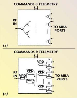
Fig. 6 Beam forming networks; (a) switched BFNs and (b) variable BFNs.
The two basic types of beam forming networks are described in greater detail in the following sections, including typical performance parameters for the switch, VPD and phase shifter building blocks in various frequency bands. As will be seen, numerous variations on the basic schematics are possible, including:
• addition of fixed power dividers to implement multiple simultaneous beams from a switched or variable BFN
• combinations of switched and variable BFNs to yield switched-beam antennas with adaptive nulling on the selected beam
• switch trees broken up into independent sub-trees to feed horns in triplets or septets to control sidelobes
• multiple-input-multiple-output switch networks including cross-strap switch matrices and redundancy rings
Switched Beam Forming Networks
The simplest type of beam former uses only microwave switches. These switches may be latching ferrite circulators configured as single-pole double-throw (SP2T) switches, or some type of solid state switching element. This type of BFN does not allow pattern shaping other than that which is provided by the fixed feed horn design. This type of BFN is used, for example, when time division multiple access (TDMA) hopping spot beams are desired from the satellite, or when the satellite must switch between multiple mobile earth terminals.
Switched BFN Building Blocks and Typical Performance
The basic building block of most spaceflight heritage passive switched BFNs is the ferrite Y-toroid switch. An example of a 20 GHz switch triad in a unibody housing is shown in Figure 7.

Fig. 7 A 20 GHz switch triad in a unibody housing.
The chief advantages of the ferrite switch are low insertion loss, high power handling capability and low DC power consumption. The low power consumption results from the fact that the ferrite switch is a latching device; it only consumes power when its remanent state is being changed. Between switching events, the electronic drivers that generate the switching pulses can be powered off.
Typical Performance of Switched BFN Components
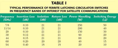
Table 1 shows typical RF performance for ferrite latching circulator switches. Switching time for all of these switches is less than 1 µs; switching times less than 500 ns can be achieved at frequencies of 20 GHz or higher. Switching rates in the tens of thousands of switching events per second are routinely achieved. Reliability of a ferrite circulator switch is 0.1 FITS in the spaceflight environment. This reliability value is independent of the number of actuations the switch sees in its lifetime.
Example of a Switched BFN — The ACTS Downlink BFN
NASA’s Advanced Communications Technology Satellite (ACTS) was launched in 1993 and serves as a test bed for Ka-band data communication satellite technology. It operates with an uplink band of 28.9 to 30.0 GHz and a downlink band of 19.2 to 20.2 GHz. The spacecraft carries two offset Cassegrain-fed multiple beam antennas, one for transmit and one for receive. The 2.2-m diameter receive MBA and the 3.3-m diameter transmit MBA both produce approximately 0.3° beam widths, giving a spot beam coverage about 120 miles in diameter on the earth. Each MBA has two switched beam forming networks, for a total of four on the spacecraft. The two BFNs are configured to serve, respectively, the East and West families of hopping spot beams.
Figure 8 shows the scan sector of the ACTS transmit West beam forming network. The schematic of the transmit West BFN is shown in Appendix A. Insertion loss through this BFN was less than 0.5 dB for the isolated spots and less than 1.0 dB for the scan sector spots. This BFN had an interesting feature in that the antenna required the scan sector horns to be excited in equal-amplitude-equal-phase triplets in order to illuminate the reflector for the desired performance. Thus the switch network had to be broken up into three interleaved binary switch trees that were phase matched to within a few degrees.

Fig. 8 ACTS transmit BFN.
The ACTS BFN switches beams in less than 850 ns and can switch between the component beams at rates up to 14,000 switching events per second per switch. It was required to handle 45 W of transmitter power and was successfully tested to 65 W.
Variable Beam Forming Networks
A variable beam forming network allows any combination of the MBA’s ports to be illuminated with any desired distribution of RF amplitude and phase. It makes use of all of the degrees of freedom of the multiple beam antenna and yields numerous operational capabilities including continuous pattern shaping and adaptive nulling of interference sources.
Variable BFN Building Blocks and Typical Performance
The building blocks of passive variable BFNs are ferrite variable power dividers (VPD), phase/amplitude control modules (PAC) and phase shifters. As with the switches, ferrite PACs, VPDs and phase shifters offer low insertion loss, high power handling capability and low DC power consumption. The low power consumption results from the fact that each of these elements is a latching device — they only consume power when their remanent states are being changed. Between switching events, the electronic drivers that generate the switching pulses can be powered off. For variable BFNs, passive ferrite implementations offer another significant benefit. Because the waveguide ferrite devices are intrinsically low loss, broadband and radiation-hard, BFNs built with this technology offer excellent channel-to-channel tracking over temperature, frequency and life. BFNs with dozens of ports can readily achieve channel-to-channel tracking of a few degrees of phase at millimeter-wave frequencies. Channel-to-channel tracking through the BFN is essential for maintaining antenna pattern fidelity.
Typical Performance of Variable BFN Components
Both PACs and VPDs use ferrite phase shifters as their key microwave control components. The next two sections show how PACs and VPDs are built up from phase shifters and other components.
Variable Power Dividers (VPD)
The VPD is shown schematically in Appendix B. Figure 9 shows a spaceflight VPD from the DSCS III program. The VPD consists of two ferrite 90° phase shifters placed between a waveguide magic tee and a waveguide 90° hybrid. The magic tee performs an equal-phase, equal-amplitude split of the incoming signal, applying these divided outputs to the ferrite phase shifter inputs. The phase shifters adjust the relative phase of these two signals before they are recombined in the hybrid. Both the phase shifters and the waveguide couplers are very low loss devices. The VPD can thus divide the signal between its two outputs while incurring very little dissipation loss along either path.

Fig. 9 A DSCS III VPD constructed in reduced height WR-112 waveguide.
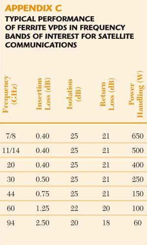
Appendix C shows typical RF performance for a ferrite VPD in frequency ranges of interest for satellite communications. The total insertion loss of the VPD is independent of the power division setting — the input power is steered to one or the other of the outputs, but the amount dissipated in the device is constant. For this reason, as well as their lower level of insertion loss, VPDs are generally preferred over PACs in variable BFNs for transmit applications.
VPDs typically have switching times in the 2 to 5 µs range. The partially magnetized state of the phase shifters in the VPD can be controlled to 12-bit resolution giving very fine granularity to the resulting amplitude setting.
Phase/Amplitude Controllers (PAC)
PACs can apply any arbitrary amplitude and phase weighting (within the unit circle) to the microwave signal passing through them. The PAC is shown schematically in Figure 10. Figure 11 shows a photograph of a spaceflight PAC in WR-22 waveguide for the MILSTAR nulling antenna BFN.

Fig. 10 Schematic of the ferrite phase shifter-based phase/amplitude control (PAC) module.
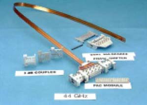
Fig. 11 Phase/amplitude controllers for the MILSTAR nulling BFN constructed in WR-22 waveguide.
The PAC consists of two ferrite 360° phase shifters placed between power dividers. The first power divider splits the incoming signal into two equal halves and applies these to the phase shifters. The two phase shifters are then adjusted such that the two halves of the signal re-combine and interfere to achieve the desired amplitude and phase for the output signal. The amplitude is controlled by the difference between the two phase shifter settings; the PAC’s phase setting is just the average of the two phase shifter settings.
Table 2 shows typical performance for ferrite PACs over the frequency ranges of interest for satellite communications. PACs are most often used in receive beam forming networks. A typical configuration would have redundant low noise amplifier modules at each port of the MBA, with each LNA module feeding into a PAC. The outputs of all the PACs are then summed in an equal N-way power combiner. In this way the component beams can be assigned any desired complex weight before being combined to yield the composite beam.

Phase Shifters
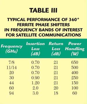
Table 3 shows typical RF performance for spaceflight phase shifters in the frequency ranges of interest for satellite communications. Switching times are typically in the range of 2 to 5 ms and the phase shifters can be switched at rates in the tens of thousands of switching events per second.
Example of a Variable BFN — DSCS III
The DSCS III reconfigurable MBAs are probably the closest to the flying antennas that will be required for the next generation of commercial communications satellites. Figure 12 shows a flightset of DSCS III variable beam forming networks. In the foreground are the two 19-port transmit BFNs and behind is the 61-port receive BFN. The receive BFN offers full amplitude and phase control of its ports. Each feed horn is connected to a 360° phase shifter, the outputs of which go to a binary VPD tree. The transmit BFNs use amplitude control only, consisting of just a binary tree of VPDs. The transmit BFNs have less than 2 dB loss. The receive BFNs have less than 3 dB loss.

Fig. 12 A flight set of DSCS III variable beam forming networks.
The DSCS BFNs are sufficiently well temperature-controlled by the spacecraft that electronic temperature compensation is not used in routine operation. The driver and control electronics are in fact often powered off completely for months at a time between reconfigurations of the antenna beams. The use of passive remanent devices for BFN weight setting elements thus results in power consumption savings as well as operational simplicity.
The photo of Figure 12 also illustrates how the beam forming network lends itself to innovative packaging solutions. DSCS III uses waveguide lens MBAs that are fed by arrays of feed horns in the focal plane. As can be seen in the photo, the BFN is actually wrapped around the circumference of the lens and serves as part of the structure holding the feed horn cluster. With a collaborative design process, the BFN provider and antenna designer can take advantage synergies such as this to minimize overall system size and mass.
The ferrite-based passive beam forming network provides a cost-effective, well-proven approach to achieving on-orbit reconfigurability of the antenna patterns of a spacecraft. BFNs can provide simple switched spot beams or continuously variable beam shapes. Figure 13 shows a sampling of the current spaceflight heritage of passive beam forming networks.
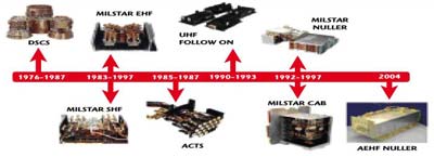
Fig. 13 Sampling of space flight heritage in passive beam forming networks.
References
- L.J. Ricardi, “Multiple Beam Antennas,” Chapter 6, Handbook of Antenna Design, Vol. 1, Peter Peregrinus Ltd., London, England, UK, 1982.
- C. Chandler, L. Hoey, D. Hixon, T. Smigla, A. Peebles and M. Em, “Ka-band Communications Satellite Technology,” Conference on Satellite Systems, Montreal, Canada, May 2002.
- T.E. Sharon, “Beam Forming Networks for mm-Wave Satellite Communications,” Microwave Journal, Vol. 26, No. 8, August 1983, pp. 105–116.
- Figures 4 and 5 are published with permission from Gedney, et al., The Advanced Communications Technology Satellite, SciTech Publishing, 2000.
Wyman L. Williams received his BS in electrical engineering from the Rose-Hulman Institute of Technology in 1980, his SM in electrical engineering from the Massachusetts Institute of Technology in 1982 and his PhD in electrical engineering from the California Institute of Technology in 1989. His professional experience includes work as a design engineer at AT&T Bell Laboratories and Dynamics Technology Inc., and as vice president of engineering at MetriWave Inc. He joined EMS Technologies in 1991. His work at EMS has included systems engineering for the MILSTAR adaptive nulling antenna beam former as well as the design of numerous microwave control components and subsystems. He served as director of engineering and is currently vice president of advanced engineering. In this role he provides technical support for business development activities and leads the strategic planning of the division’s research and development. He is a member of the IEEE and has contributed to numerous technical publications.
James M. Howell received his BS and MS degrees in electrical engineering from the Georgia Institute of Technology in 1963 and 1964, respectively. He worked at Raytheon Co. for thirty years, making contributions in the design of radar and electronic warfare systems as well as a wide variety of antenna designs (arrays, reflectors, lenses). He joined EMS Technologies in 1996, where he has served as corporate chief engineer and as a technical fellow. His contributions at EMS have been in the areas of radar, EW, antennas, adaptive nulling and satellite communications systems. He is a fellow of the IEEE and holds ten US patents. He has contributed to numerous technical papers.

