Microwave signals play an important role in modern communication architectures and radar applications. Used as carriers and signals for up and down conversion they have to comply with certain quality standards. The most important two are frequency drift, which is a measure of the long-term frequency stability, and phase noise, which is a measure of the short-term stability. To achieve the standards demanded by industry for many applications, it is desirable to use a phase-locked loop (PLL). This article introduces a new range of X- and Ku-band microwave prescalers and shows their versatility for such applications.
The company offers X- and Ku-band prescalers with a very broad field of application ranging from mini links (point-to-point/point-to-multipoint microwave connections) up to very small aperture terminal (VSAT) and high quality low noise block (LNB) products. Being an important part of the microwave synthesizer, these prescalers mean that an inexpensive low frequency PLL can be operated in an architecture with an X- or Ku-band VCO. As the range of prescalers described uses SiGe technology, the overall cost of the sub-unit (Ku-band synthesizer) can be reduced significantly.
Technical Features
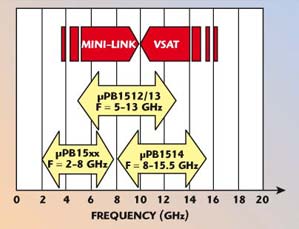
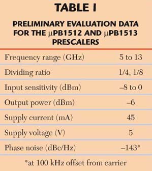
Figure 1 shows the frequency range for the intended applications of the new prescaler series. Table 1 shows preliminary evaluation data for the µPB1512 and µPB1512 prescalers as examples. These are the first models to be released and both serve the same middle frequency range of 5 to 13 GHz. However, as can be seen from the data, the difference between them is the dividing ratio. The µPB1512 has a dividing ratio of eight, whereas the value for the µPB1512 is four. The prescalers for the lower frequency range (2 to 8 GHz) and upper frequency range (8 to 15.5 GHz) are still in the development phase with design samples for the upper one available.

Fig. 1 The µPB1512/13 prescaler’s frequency range

The devices have a low internal operating voltage of 3 V, but due to the use of internal voltage regulators the supply voltage is 5 V with 10 percent tolerance for convenient biasing. Having an input sensitivity of –8 to 0 dBm (preliminary data), the devices are versatile. Figure 2 shows that the range of input sensitivity is quite wide with the specified region referred to being only a minor part of it. The graph also shows that the temperature dependency of the device is low and that the input sensitivity only dips to lower frequencies with rising temperatures.

Fig. 2 The µPB1513 prescaler’s input sensitivity at Vcc = 5 V.
As the working principle of a prescaler from any manufacturer is digital, the output signal of these devices appears more rectangular at the output, and therefore produces a certain amount of harmonics. This is shown in Figure 3. The difference between the ‘new’ divided fundamental frequency of 1.5 GHz (resulting from a 12 GHz input signal) and the higher harmonics is 16 dBc. However, this behavior is not a disadvantage when the prescaler is followed by a PLL. A rectangular signal exhibits more sharp edges that can be dealt with more easily by the PLL-internal dividers.

Fig. 3 The µPB1513 prescaler’s output spectrum with a 12 GHz input signal.
The prescalers feature a differential input and output, but can also be used as a single (unsymmetrical) input and output by terminating one input or output pin. The residual phase noise (the phase noise that is introduced by the prescaler itself) is important as it indicates the amount of phase noise that is added by the prescaler. For the NEC devices it is extremely low. The device comes in a very small plastic package and the dimensions are shown in Figure 4.

Fig. 4 The 8-pin lead-less Minimold package outline.
The Demonstrator
To show the benefits of the new prescalers a demonstrator was built that generates a 12 GHz signal in the X-band. The block diagram of the system is shown in Figure 5. The oscillator uses the NEC GaAs FET NE4210S01 as an active element and is stabilized with a dielectric resonator in order to achieve the required phase noise specifications. The PLL was built using a standard 2 GHz PLL IC.

Fig. 5 Block diagram of the demonstrator system.
A reasonable portion of the oscillator output signal is resistively branched off to the prescaler, where it is divided by a factor of eight and then transferred to the PLL. This gives a 1.5 GHz input frequency. As for generating the reference frequency, a standard 10 MHz crystal oscillator was used. The phase comparison of the reference and the divided voltage-controlled dielectric resonator oscillator (VCDRO) signals is done at 1 MHz. As mentioned earlier, an important parameter is phase noise. At 12 GHz the demonstrator displayed phase noise of –77 and –106 dBc/Hz at 10 and 100 kHz offset, respectively.
Conclusion
A new range of prescalers that simplifies the design of X- and Ku-band synthesized sources has been introduced. These devices feature inexpensive SiGe technology and come in a low cost plastic package. They are operated from single 5 V supplies that also simplify the design.
NEC Electronics (Europe) GmbH,
Düsseldorf, Germany,
e-mail: rf-info@ee.nec.de.
