A key challenge in automotive product design is the compliance to electromagnetic compatibility (EMC) and interference (EMI) requirements in a cost-driven project environment. Traditionally, EMC and EMI issues are solved in the EMC lab, often without getting a full understanding of the underlying effects. The adoption of 3D field simulation provides an insight into the root causes of electromagnetic resonance effects occurring in the product, enabling fast design cycles and high product quality.
The most sensitive electronic device from a customer point of view is the car radio. Any internal or external noise sources lead to unwanted disturbances. The automotive OEM’s spend a considerable amount of time and money to avoid such effects or reduce them to a minimum. Without special filtering, a significant disturbance signal in GSM D-net can be measured between 890 and 940 MHz.
This article shows an example of using 3D EM simulation with CST MICROWAVE STUDIO®for solving a GSM immunity issue. After setting up a model with the relevant electrical and mechanical components, a combination of several effects that introduce disturbances to the system has been found. The system could then be optimized within a few days by simulating the whole device architecture, leading to a reliable and cost-effective solution.
These signals also propagate to the loudspeaker lines. The GSM pulse (217 Hz) from a GSM mobile phone is demodulated in the audio amplifier. In the car, the GSM pulse can be heard clearly, which is not acceptable for the customer.
In order to investigate these effects and to come up with corresponding techniques, the device is simulated with 3D simulation software. The CAD model (e.g. from CATIA) is imported and the material properties of the different parts are adjusted for 3D field calculation. As a first step, the bare electronic device (car radio) is illuminated with a plane wave in the frequency range of interest.

Figure 1 3D magnetic field plot at 920 MHz inside the radio enclosure.
Figure 1 shows a 3D magnetic field plot at 920 MHz inside the radio enclosure. The red color highlights areas with high magnetic field strength; the blue color indicates regions with small or zero magnetic field strength. Shown by the red regions in Figure 1, there is a resonance effect in the metallic enclose. Now the real work begins for EMC engineers: Why does this resonance occur at all?
Experience tells us that the resonance effect might come from the audio amplifier surround with its aluminum cooling bracket. There is a resonance cavity, created by the amplifier holder, the electrolyte capacitors, the PCB structure and the cooling bracket (made of aluminum).
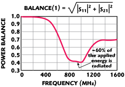
Figure 2 Power balance plot for aluminum cooling bracket.
As a first step, it is interesting to check what happens if the aluminum cooling bracket is fed with a wideband signal and how much energy is lost due to emission effects. This can be easily done by investigating the power balance, i.e. the relation of applied power and the power that is coupled out through all ports in the system. If the power balance is equal to 1, all the energy is kept in the system and there is no emission effect. If the power balance is smaller than 1, there is radiation of EM fields by the structure. In case of the aluminum cooling bracket, there is actually an imbalance of power in frequency range above 200 MHz. A maximum of about 60 percent of the applied energy is radiated in frequency range between 800 MHz and 1 GHz as shown in Figure 2.
Since one weakness of the system is known, one can concentrate on this in more detail. All parts that are not relevant for the further investigations can be removed from the model to increase simulation speed. Some probes are placed into the amplifier region in order to calculate the electric field in the cavity. The structure is illuminated with an electromagnetic plane wave again as shown in Figure 3a.

Figure 3 EM wave propagation direction (a) and E-fieldmagnitude vs. frequency for the amplifier region (b).
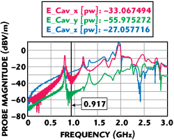
Figure 4 E-field magnitude vs. frquency without electrolyte capacitors.
There is a strong resonance at 917 MHz for all three geometrical E-field components x, y and z as shown in Figure 3b. What is causing the resonance at 917 MHz? Maybe the electrolyte capacitors?
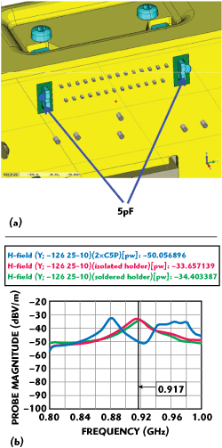
Figure 5 Location of capacitors added to PCB GND (a) and E-field magnitude vs. frequency plot (b).
One can try it again, removing them in a second simulation. The results are shown in Figure 4. There is no resonance anymore at 917 MHz for all three geometrical E-field components so this is an improvement. This information is quite helpful in order to tune the resonance cavity. Instead of crimping the amplifier holder directly to the PCB (and to the PCB GND structure), the idea is to connect the holder by means of 5 pF capacitors to PCB GND as shown in Figure 5a.
As an effect, the capacitance between the crimp pad and PCB GND reduces the impedance between the housing and PCB GND around 900 MHz and reduces the quality of the cavity as shown in Figure 5b. There is no resonance effect left. That had not been possible by isolating or soldering the holder to PCB GND. The effect can be also seen in the 3D field plot at 920 MHz, shown in Figure 6.
Removing the audio input filter capacitors from the floor of the cavity reduced the coupling from the mobile phone to the car radio tremendously. The basic idea of soldering the amplifier holder to the PCB GND system by means of a 5 pF capacitor could be verified by a series of simulations. Final measurements of the loudspeaker spectrum proved the simulation results to be correct. The measured loudspeaker spectrum of the original system is shown in Figure 7a compared to the loudspeaker spectrum after performing the changes shown in Figure 7b.
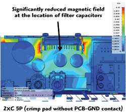
Figure 6 3D magnetic field plot at 920 MHz inside the radio enclosure after improvements.
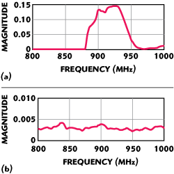
Figure 7 The measured loudspeaker spectrum before changes (a) and after improvements (b).
In summary, there were several problems that led to the EMC problems in the car radio:
- Aluminum cooling bracket and amplifier holder act as 900 MHz broadband antenna
- The space between audio amplifier/holder, cooling bracket, and electrolyte capacitors of the power supply act as resonance cavity at 917 MHz and amplifies the disturber
- Contact of housing-GND to PCB-GND has an impact on the cavity resonance quality and frequency
- Capacitors placed in the resonance cavity pick up the disturber and feed it to the amplifier
It is important to note that only a deep understanding of all of these effects helped the engineers find a solution because every effect took part in the EMC problem. Without accurate simulation, it had not been possible to optimize the system.
