With the rapid development of communication technology, there have been increasing demands for advanced radio frequency (RF) filters with small size, wide stopband and high selectivity. To realize better selectivity, the generation of transmission zeros is very important in the synthesis of modern filters. Most of the research efforts are focused on filters where both the source and the load are connected to only one resonator.1,2 Such filters can generate at most N-2 finite transmission zeros with N-coupled resonators. However, when source/load coupling is involved, N finite transmission zeros from N-coupled resonators can be obtained.3-6
In order to improve the performance of out-of-band rejection, a number of technologies have been widely investigated. For example, utilizing stepped impedance resonators (SIR) or slow-wave resonators is the convenient method to realize wide stopband.7-9 In addition, a feeding scheme with L-shaped lines has been proposed to suppress the harmonic.10 Although conventional slow-wave resonators possess the advantages of miniaturization and a wide stopband, these filters suffer from loose coupling between resonator and feeding line, resulting in high external quality factor.
In this article, a two-order filter, operating at 2.4 GHz for application in a wireless local area network (WLAN) system, is proposed. Two slow-wave resonators and corresponding feeding structures are introduced to enhance the tunable range of the external quality factor. Using source/load coupling can realize two controllable transmission zeros. Measured and simulated results show that this filter cannot only obtain high selectivity, but also achieve wide upper stopband as well.
Filter Design

Figure 1 Layout of the proposed microstrip BPF.
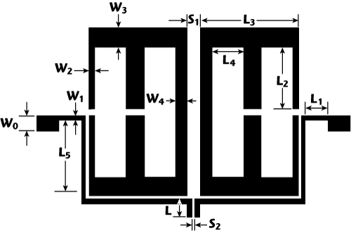
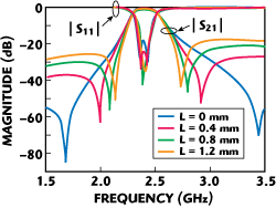
Figure 1 shows the layout of the proposed microstrip BPF using two slow-wave resonators. Figure 2 illustrates the structure of the proposed slow-wave resonator. Two opposite open stubs are added inside of the slow-wave resonator to achieve a compact size. Compared with the conventional slow-wave resonator, it results in a smaller external quality factor. The required 2.4 GHz center frequency of the BPF (as specified in the IEEE 802.11a/b standard for WLAN), is obtained by adjusting the size of the resonator and the position of open stubs. In Figure 3, the simulated results show the frequency responses of the proposed BPF under different source/load coupling lengths L. The length L is introduced to provide source/load capacitive coupling. When L increases from 0 to 1.2 mm, the return loss in the passband is reduced, while a pair of transmission zeros is closer to the passband. Thus, sharper fall-off at both passband edges can be achieved.

Figure 2 Structure of the slow-wave resonator: (a) novel resonator and (b) conventional resonator.

Figure 3 Simulated frequency responses of the proposed BPF for different source-lead coupling lengths.
According to the above analysis procedure, the dimensions of the filter are obtained as follows: L = 0.6 mm, L1 = 1.5 mm, L2 = 5.2 mm, L3 = 8.4 mm, L4 = 1.7 mm, L5 = 7.2 mm, W0 = 2.1 mm, W1 = 0.4 mm, W2 = 0.6 mm, W3 = 1.8 mm, W4 = 1.2 mm, S1 = 1.2 mm and S2 = 0.2 mm. The thickness of the substrate used here is 0.8 mm, and its relative dielectric constant is 2.78.
Measured Results
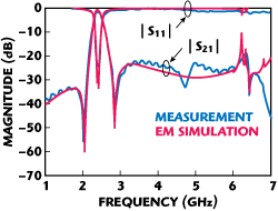
A photograph of the fabricated BPF is shown in Figure 4. The S-parameters are measured by using a network analyzer, Agilent 8722ES, and are plotted in Figure 5 together with EM simulated results. The measured results show a return loss of 24 dB, a minimum insertion loss of 1.66 dB in the passband, FBW of 3.3 percent at 2.4 GHz, and better than -20 dB rejection level in the upper stopband, up to 7 GHz. Two transmission zeros are clearly observed at 2.01 GHz with -56 dB attenuation and 2.88 GHz with -41 dB attenuation. The insertion loss is mainly attributed to the SMA connector and the conductor and dielectric losses. Due to the pair generation of transmission zeros on both sides of the passband, a better selectivity is realized.

Figure 4 Photograph of fabricated microstrip bandpass filter.

Figure 5 Comparison of simulated and measured frequency responses.
Conclusion
A novel microstrip bandpass filter, using slow-wave resonators, is presented. The measured results show good characteristics, such as low insertion loss in the passband, a wide upper stopband and high passband selectivity. This performance agrees closely with the simulation. With these features, the proposed BPF is suitable for WLAN applications.
Acknowledgments
This work is supported by the Shanghai Natural Science Foundation (10ZR1411900) and the Leading Academic Discipline Project and STCSM (S30108 and 08DZ2231100) and the Graduate Student Innovative Foundation of Shanghai University (SHUCX092127).
References
- C.S. Ahn, J. Lee and Y.S. Kim, “Design Flexibility of an Open-loop Resonator Filter Using Similarity Transformation of Coupling Matrix,” IEEE Microwave and Wireless Components Letters, Vol. 15, No. 4, April 2005, pp. 262-264.
- Y.M. Chen, S.F. Chang, C.C. Chang and T.J. Hung, “Design of Stepped-impedance Combline Bandpass Filters with Symmetric Insertion-loss Response and Wide Stopband Range,” IEEE Transactions on Microwave Theory and Techniques, Vol. 55, No. 10, October 2007, pp. 2191-2199.
- X.C. Zhang, Z.Y. Yu and J. Xu, “Design of Microstrip Dual-mode Filters Based on Source-load Coupling,” IEEE Microwave and Wireless Components Letters, Vol. 18, No. 10, October 2008, pp. 677-679.
- Y.X. Wang, B.Z. Wang and J.P. Wang, “The Design of a Coupled Resonator Bandpass Filter with Wide Stop-band,” IEEE Microwave and Wireless Components Letters, Vol. 18, No. 4, April 2008, pp. 251-253.
- R.J. Cameron, “Advanced Coupling Matrix Synthesis Techniques for Microwave Filters,” IEEE Transactions on Microwave Theory and Techniques, Vol. 51, No. 1, January 2003, pp. 1-10.
- U. Rosenberg and S. Amari, “Novel Coupling Schemes for Microwave Resonator Filters,” IEEE Transactions on Microwave Theory and Techniques, Vol. 50, No. 12, December 2002, pp. 2896-2902.
- C.W. Tang and M.C. Chen, “Wide Stopband Parallel-coupled Stacked SIRs Bandpass Filters with Open-stub Lines,” IEEE Microwave and Wireless Components Letters, Vol. 16, No. 12, December 2006, pp. 666-668.
- Y.C. Chang, C.H. Kao, M.H. Weng and R.Y. Yang, “Design of the Compact Wideband Bandpass Filter with Low Loss, High Selectivity and Wide Stopband,” IEEE Microwave and Wireless Components Letters, Vol. 18, No. 12, December 2008, pp. 770-772.
- J.S. Hong and M.J. Lancaster, Microstrip Filters for RF/Microwave Applications, John Wiley & Sons, New York, NY, 2001.
- X.D. Huang and C.H. Cheng, “A Novel Microstrip Dual-mode Bandpass Filter with Harmonic Suppression,” IEEE Microwave and Wireless Components Letters, Vol. 16, No. 7, July 2006, pp. 404-406.
