Over the past 20 years, RF and microwave signal generators have grown in capability and complexity in order to keep pace with the swift advances of vector modulated communications and advanced radar systems. One of the most critical performance parameters for these applications is phase noise.
Purchasing an off-the-shelf signal generator for an application that demands low phase noise can be costly. Low phase noise is often the most expensive performance option available with a high-end signal generator. There are several steps that can be used to improve and optimize the phase noise performance of a signal generator, provided it allows access to the reference hardware, voltage-controlled oscillators (VCO) and phase lock loops (PLL) that make up the synthesizer chain. Before these steps are explored, it will be helpful to have a quick look at how the phase noise is specified.

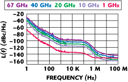
Figure 1 Absolute SSB phase noise at various carrier frequencies.
Phase noise is random fluctuations in the phase of a signal, contributed by the various components and circuits within a generator, which disperses the output power to the surrounding frequencies. Ideally, the power of a synthesized continuous wave (CW) signal is all located at a single frequency. This can be modeled as random phase modulation. The units of phase noise (referred to as L(f)) are measured in dBc/Hz or dB down from the measured carrier power in a 1 Hz bandwidth for frequency offsets from the CW output. For example, the phase noise of a generator may be specified as -97 dBc/Hz at 100 kHz offset from a CW frequency at 20 GHz. The phase noise is generally plotted on a log-log chart to easily examine both the close-in phase noise (offsets < 1 kHz) and the far-out phase noise (offsets > 10 kHz). See Figure 1 as an example.
Sources of Phase Noise Within a Signal Generator

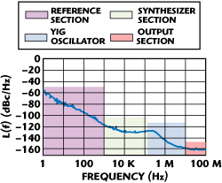
Figure 2 Source of phase noise within a signal generator for different offsets.
There are four main contributors to phase noise in a signal generator: The frequency reference, the synthesizer (phase detectors and PLLs), the oscillator and the broadband noise floor. Figure 2 indicates which section of the signal generator hardware dominates the different portions of the phase noise characteristics.
At frequency offsets below approximately 1 kHz, the stability and phase noise are determined by a reference section that is usually driven by an initial 10 MHz signal. The 10 MHz frequency reference can be generated internally or supplied externally. The frequency reference section multiplies the fall-off initially as 1/f3 and transitions to a 1/f2 dependence, which on a log-log plot represents a slope of 20 dB per decade.
Generally, low phase noise signal generators use an yttrium iron garnet (YIG)-based oscillator, which has better performance than typical VCOs. The phase noise of YIG oscillators falls off more quickly for far from carrier offsets above 100 kHz. They exhibit a wide tuning range, meaning there is less multiplying of the signal required to achieve the desired frequency, leading to lower phase noise, particularly at higher frequencies. The bandwidth of the PLL determines the point at which the YIG oscillator contribution to the overall phase noise becomes suppressed. For frequency offsets inside the PLL bandwidth, the overall phase noise of the generator is dependent upon contributions from the phase detector and the reference oscillator.
The broadband noise floor results primarily from the thermal noise present in the generator; most of this is contributed by the power amplifier in the output section. Generally, the phase noise at offsets greater than 10 MHz is limited by this noise floor. This far from carrier noise most affects wideband communication systems, particularly those using orthogonal frequency division multiplexing (OFDM). The closely spaced multiple carriers can begin to interfere with one another, if the phase noise at offsets that approach the carrier spacing is too high.
Suppressing Phase Noise Inside the Signal Generator
Test equipment manufacturers are always looking to make advances in signal generator architecture that will suppress phase noise to new lows. One of the most basic ways to improve phase noise, particularly close-in, is to install a lower noise 10 MHz reference. These are normally oven controlled crystal oscillators (OCXO) that are stabilized with respect to temperature. Research laboratories are constantly looking to improve reference technology and these advances have quickly made their way into signal generator products available today.
New and innovative designs are emerging to suppress phase noise to new levels in the areas of the phase noise plot dominated by the synthesizer section and the YIG oscillator. These advanced architectural improvements to the reference and synthesizer design include well devised frequency plans to minimize spurious signals, multiple loop design for enhanced stability and the ability to drive the loops harder, enabling a higher signal-to-noise as the signal traverses the synthesizer chain.
Taking Advantage of Low Residual Phase Noise

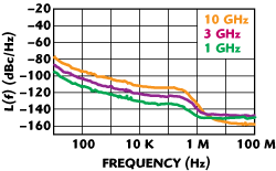
Figure 3 Residual phase noise of a signal generator.
The residual phase noise represents the phase noise of a signal generator, not including the reference section. The plots in Figure 3 show the residual phase noise levels of the same signal generator as the absolute phase noise plots in Figure 1. The absolute phase noise in the plot indicates the typical and total phase noise of the signal generator from one end of the block diagram to the other. How can this low residual phase noise be used to our advantage?

Figure 4 Adjusting the PLL integrator/ filter bandwidth of the reference and YIG oscillator loops within the signal generator.
Most signal generators provide a port to supply an external 10 MHz reference. This way, using a very clean reference can help reduce close to carrier phase noise, although it will remain far above the residual levels. The reference section of a signal generator consists of much more than the 10 MHz reference. It includes a phase detector and PLL as well as multipliers to supply multiple frequencies in a range usable by the rest of the synthesizer chain (see Figure 4). In order to bypass the reference, a higher frequency reference must be supplied externally.
A higher frequency external reference can be used to drive the phase noise of the signal generator down toward residual levels. The signal generator would have to allow for access to the reference path past the reference section and the external high frequency reference source used would have to have lower intrinsic phase noise than the signal generator’s internal reference. Many high performance signal generators have internal references that already provide excellent phase noise characteristics. The new reference would have to exhibit exceptional phase noise performance.
Optimizing Phase Noise Performance for Your Application
The loop bandwidth of the PLLs within a signal generator refers to the bandwidth of the integrating filter that follows the phase detector (see Figure 4). There are multiple PLLs within the reference and synthesizer paths, each of which affects the phase noise in its own way. In most signal generators, these bandwidths are fixed at a point considered optimal for most use cases. The loop bandwidth of the reference oscillator and the YIG oscillator (YO) PLLs may be used to optimize the phase noise in certain areas of offset from the carrier. This requires that the signal generator provide adjustment of the bandwidth.
Adjustment of the reference loop bandwidth is generally enabled in fixed steps for either an internal or external frequency reference, usually ranging from 25 to 650 Hz. This adjustment affects the slope of the phase noise curve up to an offset of approximately 2 kHz. The higher the reference loop bandwidth, the lower the phase noise at very low offsets, less than approximately 200 Hz. For a lower reference loop bandwidth, there is a small reduction of the phase noise in the offset range from approximately 200 Hz to 2 kHz. Optimizing for one offset range is at the expense of the other.

Figure 5 Optimizing the YIG oscillator loop bandwidth.
New synthesizer designs enable access to the YO loop bandwidth in addition to the reference loop, where previous designs did not. Adjustment of the YO loop bandwidth affects an entirely different part of the phase noise plot. With this adjustment, the phase noise at offsets from approximately 1 kHz to 1 MHz is affected. Setting the YO loop bandwidth to a wide range of approximately 240 kHz optimizes the phase noise at offsets greater than 150 kHz. Setting the YO loop bandwidth to a narrow range of approximately 130 kHz optimizes phase noise for offsets below 150 kHz (see Figure 5).
Use of Dividers at Lower Frequencies, Instead of Heterodyne Mixing
Signal generators often use dividers to provide their coarse frequency adjustment. When a carrier signal is routed through a frequency divider, the carrier frequency is reduced by the divide number (n):

where Fin is the input frequency and n is the divide number.
In the case of a divider where n = 2, the output frequency is one half of the input frequency.
In addition to the reduction in the carrier frequency, the carrier phase noise is reduced by a 20log(n) factor:

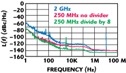
For the example of a divide-by-two divider, the output frequency’s phase noise will be 6 dB lower (20 log 2) than the phase noise of the input frequency, as indicated by the phase noise plots shown in Figure 1. When using frequency or phase modulation (FM or PM) in a signal generator, dividing a carrier frequency will reduce the FM deviation and the PM deviation by a factor of 1/n. At lower carrier frequencies, the modulation deviation can become too small to be useful. Many signal generators switch to a heterodyne mixing scheme instead of dividing at lower frequencies in order to preserve modulation bandwidth. Note that heterodyne mixing to lower frequencies does not provide phase noise reduction. In Figure 6, the phase noise of a 250 MHz signal is shown both divided down from a 2 GHz signal and mixed down.

Figure 6 Phase noise advantage of using dividers.
Frequency dividers can be used externally and some signal generators have integrated dividers. When enabled, the generator uses a dividing technique to output signals at low frequencies. This results in improved phase noise at all offsets for these frequencies. The dividers can be disabled, returning the signal generator to a standard mode of creating low frequencies with a heterodyning technique. This mode provides wider deviation bandwidth for FM and PM signals.
Conclusion
Test and characterization of RF and microwave components and systems, particularly receivers, generally requires the presence of a clean test stimulus. Classic test engineering methodologies dictate that the signal stimulus must have performance fidelity of at least an order of magnitude better than the device or system being characterized. Otherwise the risk is run of contaminating the results with the anomalies of the stimulus source. Some of the steps that can be taken to ensure the best possible performance from a signal generator have been discussed. More information on measurement science and test instrumentation can be found on manufacturer’s websites such as Agilent.
