
There are many applications that are presently being researched in the high millimeter-wave/low terahertz frequency range. These applications are supporting many areas, including astronomy, remote sensing, communications, radar systems and homeland security. This standard is being developed to make sure that all of these applications have a commonality and can interface easily with other technologies that are being developed.

Frequency Bands and Waveguide Dimensions
To date, much of the work of the Working Group has concentrated on establishing the frequency bands and waveguide dimensions. It was agreed early on that, for the waveguide aperture, the ratio of the width to height of the waveguide would be 2:1. The waveguide sizes and frequency bands that have been chosen to be included in the standard are shown in Table 1.1 The waveguides in the shaded region of Table 1 correspond closely to waveguides given in existing standards (References 2 and 3, for example). The main difference is that the IEEE waveguide sizes are being specified using metric units (that is micrometers, rather than mils that were used, for example in Reference 2). The waveguides will also be named according to their metric size: the letters WM indicate that the size refers to waveguide using metric dimensions, followed by a number indicating the size (in micrometers) of the broad wall dimension of the waveguide. For example, WM-570 refers to a waveguide with a broad wall dimension of 570 µm. Another difference with the IEEE standard is that it will use tighter tolerances for specifying the critical dimensions of the waveguide (that is those dimensions that directly affect electrical performance).

For information, Table 2 gives a comparison between the new IEEE waveguide names1 and the names of related waveguides in the existing MIL standard,2 and the nearest waveguides that have been proposed previously to extend the MIL series of waveguides.4
The series of waveguides shown in Table 1 have been chosen so that they can be easily extended, when necessary, to cover higher frequencies. The following procedure should be followed to extend the waveguide series:
- Select a waveguide size from the unshaded region of Table 1;
- Divide the mechanical dimensions by 10;
- Multiply the frequency values by 10;
- Rename the waveguide accordingly.

For example, the next two sizes in this series (derived from WM710 and WM-570) are shown in Table 3.
The part of the standard covering frequency bands and waveguide dimensions has now been drafted and is likely to be circulated for public comment in the coming few months.
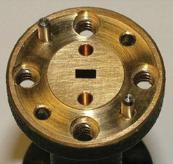
Figure 1 A precision version of the so-called "UG-387" flange, showing the two additional dowel holes, immediately above and below the rectangular waveguide aperture.
Waveguide Interfaces
The attention of the standard’s Working Group is now turning to the waveguide interfaces, often called “flanges”. The Working Group is keen to ensure that it considered all flange designs that are used regularly at these frequencies (that is at 110 GHz and above). Therefore, a subgroup is being set up to investigate this matter further. Advice is also being sought from the entire millimeter- and submillimeter-wave communities to help identify any such candidate flange designs. If you are aware of any flange design that you consider should be included in this standard, please contact the authors of this article. The plan is that the standard, when published, will contain all appropriate flanges that will be used routinely in this frequency region.
For example, one such flange that is likely to be considered for inclusion in the standard is a precision version of the MILF-3922-67D flange (often called UG-387) that has been described5 and is shown in Figure 1. Compared to the conventional UG-387 flange,6 this precision version contains two additional alignment dowel holes immediately above and below the waveguide aperture. These additional holes (and the associated dowel pins) are specified to a tighter dimensional tolerance than the dowel holes and pins found on the conventional UG-387 flange. This leads to better mechanical alignment of the waveguide interfaces and hence lower electrical reflection from a mated pair of flanges.
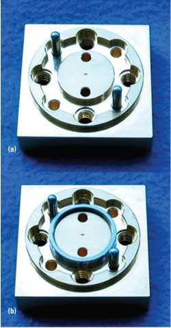
Figure 2 Ring-centered waveguide flange: (a) with dowel holes and pins and (b) with the coupling ring in place.
Another type of flange that is likely to be considered for inclusion in the standard is a newer design—a ring-centered flange,7 as shown in Figure 2. This design is compatible with both the UG-387 and precision UG-387 flange designs, but also uses a coupling ring to significantly improve the alignment of the flange interfaces.
It is expected that the IEEE standard, when published, will contain several flange designs, allowing end-users (such as customers, suppliers, etc.) to chose a design that best meets their given requirements. The role of the standard, in this context, is to provide the information needed for this choice to be made reliably.
Conclusion
The IEEE is well on its way to publishing a standard for defining rectangular metallic waveguides for use at frequencies above 110 GHz. Already, there are many applications emerging for the use of this part of the electromagnetic spectrum—millimetre-wave, submillimeter-wave, terahertz, etc.8 Therefore, the publication of this standard is timely, and should serve our industry well for many years to come.
Nick Ridler and Ron Ginley are chair and vice-chair, respectively, of the EEE P1785 working group (http://grouper.ieee.org/group/1785).
References
- N.M. Ridler, R.A. Ginley, J.L. Hesler, A.R. Kerr, R.D. Pollard and D.F. Williams, “Towards Standardized Waveguide Sizes and Interfaces for Submillimeter Wavelengths,” Proceedings of the 21st International Symposium on Space THz Technology, Oxford, UK, 23-25 March 2010.
- MIL-DTL-85/3C, “Waveguides, Rigid, Rectangular (Millimetre Wavelength),” October 2005.
- IEC 60153-2, “Hollow Metallic Waveguides, Part 2: Relevant Specifications for Ordinary Rectangular Waveguides,” Second Edition, 1974.
- J.L. Hesler, A.R. Kerr, W. Grammer and E. Wollack, “Recommendations for Waveguide Interfaces to 1 THz,” Proceedings of the 18th International Symposium on Space THz Technology, Pasadena, CA, March 2007.
- C. Oleson and A. Denning, “Millimeter-wave Vector Analysis Calibration and Measurement Problems Caused by Common Waveguide Irregularities,” 56th ARFTG Microwave Measurement Conference Digest, Boulder, CO, December 2000.
- MIL-DTL-3922/67D, “Flanges, Waveguide (contact), Round, 4 Hole (Millimeter),” December 2009.
- H. Li, A.R. Kerr, J.L. Hesler, G. Wu, Q. Yu, N.S. Barker and R.M. Weikle II, “An Improved Ring-centered Waveguide Flange for Millimeter- and Submillimeter-wave Applications,” 76th ARFTG Microwave Measurement Conference Digest, December 2010, pp. 108-111.
- J.D. Albrecht, M.J. Rosker, H.B. Wallace and T.H. Chang, “THz Electronics Projects at DARPA: Transistors, TMICs and Amplifiers,” 2010 IEEE MTT-S International Microwave Symposium Digest, pp. 1118-1121.