A new class of microstrip surface-mountable harmonic (low pass) filters constructed using thick film technology has been developed at IMS Inc. They are designed for use wherever suppression of harmonics or other spurious signals generated by transmitters operating in a host of different RF applications is required. Such applications include point-to-point communications, WLAN, broadband, low power broadcast, traffic control radar, commercial avionics, microwave radio, satellite and RF sensing, to name a few. The IMF series of semi-custom filters are of rugged alumina or AlN construction and each unit provides a level of performance that exceeds typical filters built to a catalogue specification.
Implementation of the harmonic filter is a popular method for cleaning up the spurious signals emitted by transmitters. Regardless of application, the best place to mount a harmonic low pass filter is as close to the transmitter as possible so that other components within a given circuit are not subject to harmonic distortion. In most cases this means that the output power of the transmitter must also be handled by the harmonic filter.
In high power (kilowatts) industries, such as those utilizing broadcast and military radar applications, rigid coaxial or waveguide filter construction is necessary. In the expanding fields of the previously mentioned markets, however, whose operating RF powers are typically less than 100 W, RF components such as harmonic filters, bandpass filters, hybrid couplers, etc., can be implemented in ceramic surface-mount technology (SMT) form. IMS’s SMT harmonic filters are designed for frequency bands from UHF to 10 GHz at power levels of 10 to 50 W and are ideally suited for transmitter modules where superior performance is the critical parameter.
Board level implementation of harmonic suppression functions has begun to give way to SMT component implementation due primarily to the fact that components are smaller, more rugged and are constructed of lower loss, more moisture resistant materials. In addition, the traditional connectorized RF filters are bulky, require cable connections, are labor intensive and are much more expensive than their SMT counterparts, whose insertion losses are comparable if not better than those possessed by the connectorized components.
The measured insertion losses for the IMF family of harmonic filters are also typically less than what can be achieved by filters of low temperature co-fired ceramic (LTCC) construction, whose small size limits power handling and leads to higher insertion losses, or filters implemented on FR4 or other boards of relatively low dielectric constant and high loss tangent, each of which tends to contribute to higher radiative losses (not to mention larger real estate) for a given frequency and required number of sections.

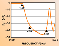
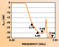
Fig. 1 Wideband insertion loss of the IMF2262 filter.

Fig. 2 Wideband insertion loss of the IMF2292 filter.
Figures 1, 2 and 3 show the measured rejection responses of the IMF2262, IMF2292 and IMF2293 harmonic filters, respectively. The seven-section IMF2262 was designed for operation up to 1450 MHz with a sharp rate of cutoff to achieve 25 dB minimum rejection at 2.4 GHz. The passband for each of the other two filters extends to 2.5 GHz and rejection levels are 20 to 25 dB at 5 GHz or better, depending on the unit.

Fig. 3 Wideband insertion loss of the IMF2293 filter.

Fig. 4 Typical narrowband insertion loss for the IMF2293 filter.
Figure 4 shows the typical narrowband measured insertion losses for the same filters. Typically, insertion losses range from 0.3 to 0.7 dB, depending on frequency and number of sections.
Note the difference in the rejection responses of the IMF2292 and IMF2293 filters. The overall dimension of the IMF2292 was wider than that of the IMF2293, thus allowing for better heat transfer from the baseplate to thermal ground, which translates to a higher power level performance. However, due to this increased width, a higher order mode crept downward in frequency, potentially encroaching on the areas where the filter was intended to reject harmonics. In order to lessen the effect of this higher order mode, the spaces between the semi-lumped/distributed capacitive sections in the IMF2292 were correspondingly increased (over those of the IMF2293), thus reducing the magnitude of the mode.
The IMF2292 is 0.322" wide while the IMF2293 is 0.184" wide. Both filters were 0.442" long, 0.025" thick and are a five-section design. The IMF2262 is a seven-section design and possesses dimensions of 0.550" × 0.400" × 0.025" thick.
Each of these filters was designed to exacting specifications and tested in matched fixtures of 50 W alumina microstrip construction. The RF performance of the fixture itself was also measured using straight sections of 50 W microstrip line, thus de-embedding the filter from the circuit and resulting in a true measured response. Measured test data shown is directly derived from a network analyzer whose cables were connected to coaxial/microstrip launches of alumina construction that is integral to the fixture.
The backplane of each filter was connected directly to thermal and electrical ground. The 50 ? microstrip transmission lines within the fixture possessed lengths exceeding a dozen wavelengths in order to aid in accurate data collection. The filters were tuned into the fixture such that the maximum VSWR in the passband did not exceed 1.2.
As is the case for any IMS harmonic filter, the design parameters are thoroughly investigated and an optimal design is created prior to manufacture, depending on the user’s needs. Typically, five- to seven-section filters fabricated in this manner will exhibit insertion losses of 0.5 dB or less, depending on frequency and the polynomial used to generate the low pass function. The company has the flexibility to implement a number of different polynomials, including Chebyschev and Zolotarev among others, in order to match filter performance to a potentially large number of exacting specifications. Different polynomials will lead to differing levels of rejection in the stopband and thus to differing numbers of sections for a given filter function.
All of IMS’ filters are designed using lumped/distributed parametric methodology such that the length of any one element is kept to a fraction of a wavelength (the length of any element, especially the inductive sections, is typically limited to ?g/8 or less), thus optimizing functionality, predictability and performance.
Generally speaking, power handling for these devices depends on the internal geometry of the filter and the temperature of the baseplate. The IMF2292 filter will handle up to 25 W if the baseplate is kept at 100°C or less. Higher power capacities are achievable with a filter of AlN construction and similar proper thermal management techniques.
These filters are available with either solderable or bondable connections, have symmetric characteristics for ease in mounting and are provided as a RoHS-compliant SMT package. Data sheets are available on the company’s Web site. Any desired low pass function will be investigated from a feasibility standpoint by the company’s engineering department.
International Manufacturing Services Inc. (IMS),
Portsmouth, RI
(401) 683-9700,
www.ims-resistors.com
