

Online Spotlight: A Low-Profile Wideband 4×4 MIMO Antenna for 5G Terminal Application
A miniaturized broadband 4×4 multiple-input multiple-output (MIMO) circular quad antenna module that can be mounted on a metal surface covers the 5G band N77 (3.3 to 4.2 GHz) and is suitable for 5G terminals. It has a radius of 22 mm and a height of 2.4 mm. Isolation between elements is greater than 10 dB and the radiation efficiency is 38 to 68 percent.
In the 4G era, smart terminal antennas were typically integrated into a metal structure.1-3 For 5G, smart devices the trend is toward miniaturization. For a planar antenna, size and profile determine its performance, including bandwidth. In addition to increasing its profile and area, there are several ways to increase its bandwidth with stacked patches.
The first is to use magnetic coupling4-6 by combining the main patch and parasitic patches with shorting pins.4-6 Similarly, bandwidth can be increased by grooving in primary and parasitic patches to achieve the fusion of different modes. A coupling feed7-9 is another effective method, which couples the gap to an upper patch to increase an antenna’s bandwidth. L-type probe feeds are often used as well to increase bandwidth.10-13 The vertical part of the L-type probe generates inductive reactance, while the horizontal part generates capacitance with the patch and the ground plane; these reactances cancel each other to produce a wide frequency band.
Liang et al.14 adapted a method of combining multiple types of stacked patches to realize broadband performance. Bandwidth is also achieved by combining high-order modes and low-order modes by increasing the resonant frequencies of the low-order modes and decreasing the resonant frequencies of high-order modes with shorting pins or etching slots vertical to the current path.15-17
 TABLE I - COMPARISON WITH OTHER WORK
Employing multiple antennas (i.e. MIMO) to emit and receive signals18-21 is an efficient use of space. See Table I, which compares the design described in this article with other reported work. In the work of Wong et al.23, 24 a broadband three antenna module uses three different senses of polarization with an angle between two adjacent antennas of 60 degrees in a height of 11.7 mm and an area of 625.27 mm2. In another example, a square four-antenna module with a height of 10 mm and an area of 1,764 mm2 covers the N77 and N78 frequency bands.25 Another approach employs an annual ring structure with a height of 10.4 mm in an area of 2,011 mm2.26 With the size of intelligent terminal equipment becoming miniaturized, however, space is becoming so constrained that antennas with a profile of 10 mm are no longer suitable for many applications.
A low-profile four-antenna module covering the 5G N77 band has a height of 2 mm and a diameter of only 30.8 mm.27 A four-antenna module with a height of 2.4 mm and an area of 1600 mm realizes wideband performance by adding a shorting pin to form TM1,1 and TM1/2,1/2 modes.28 Another four-antenna module has open slots that are connected to each other. Its height is only 1 mm.29
The antenna described in this work covers the 5G N77 band (3.3 to 4.2 GHz) with a low-profile structure suitable for mounting on metallic surfaces. Two resonant modes are excited by loading a shorting pin to achieve wide bandwidth.
ANTENNA DESIGN AND ANALYSIS
Antenna Structure
Figure 1 shows the exploded view, plan view and side view of the circular antenna. The antenna height is 2.4 mm and the size of the ground plane is 60 x 60 mm2. Since the length of the ground plane is well over half a wavelength at the antenna's lowest frequency (3.3 GHz), it does not affect antenna performance. This allows the antenna to be used on any type of metal platform.
The antenna has three parts: the bottom basal plate, the top basal plate and the air layer. The substrate material is FR4 (εr = 4.4, tanδ = 0.02), fed by a microstrip line. Four equally spaced shorting pins are placed in the middle of each quarter circle to connect the antenna to the ground plane. In practice, all shorting pins are connected by red copper wires. Dimensions of the antenna parameters shown in Figure 1 (in mm) are R1 = 4.5, R2 = 0.3, R3 = 0.5, L = 60, L1 = 18.7, L2 = 5.4, W1 = 1.6, W2 = 1, S = 3.2, H1 = 0.5, H2 = 0.5 and H3 = 2.

Figure 1 Low-profile wideband circle patch MIMO antenna: exploded view (a) plan view top surface (b), plan view bottom surface (c) and side view (d).
Design Evolution
Each port of the antenna forms two resonant modes. Cross slots with widths of 1.6 mm are etched in the circular patch to form a quarter circular resonant TM1,1 mode for each antenna port. This is the basic mode produced in the quarter-round patch. Shorting pins are then installed on a line bisecting each quarter circle. The shorting pins are located at the center of the quarter circle, which is also the location of the TM1,1 mode null, thus exciting the TM1/2,1 anti-resonant mode. Since the paths of the two resonant edges do not differ by much, the two operating modes are excited at frequencies close to each other, creating a broad operating frequency band.
In addition, the feed employs microstrip line coupling. When using a coaxial feed, the probes create a strong inductive impedance on the antenna, and the use of slot coupling can effectively mitigate the inductive impedance from the probes. This is also an efficient way to adjust impedance matching.
Figure 2a shows Case A with only cross slots, Figure 2b shows Case B with only shorting pins, Figure 2c shows Case C with both cross slots and shorting pins, which is the final structure of this design. Figure 2d indicates the resonant regions of the patch.

Figure 2 Case A – cross-slotted antenna (a) Case B – antenna with shorting pins (b), Case C – antenna with both cross slots and shorting pins (c), resonant patch regions (d).
Since the antennas are arranged in order of selection, the results for port 1 and Ports 2-4 are the same, so only the results for port 1 (i.e. Antenna 1) are given. Figure 3a shows S-parameters for Case A. The shaded area is the frequency range required for this design (3.3 to 4.2 GHz). Its center frequency is 4.064 GHz and it has a – 6 dB impedance bandwidth of 300 MHz, from 3.9 to 4.2 GHz.
Figures 3b and c show the two-dimensional simulated vector current maps of Antenna 1 at 4.060 GHz. The black arrows in Figure 3b represent the current direction. From Figures 3b and c, it is apparent that resonance occurs in the ABD region (see Figure 2). The resonant mode for Case A corresponds to the fundamental TM11 mode of the quarter-circle patch. Figure 3d shows the three-dimensional vector electric field distribution of Antenna 1 below 4.060 GHz. The electric field changes from maximum to minimum along the angular direction, after which it flips and changes from minimum to maximum. The current gradually increases along the radial direction, consistent with the TM11 mode.
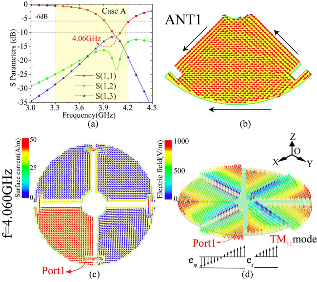
Figure 3 Case A – simulated S-parameters at Port 1 (a) simulated surface current distribution for Antenna 1 (b), simulated surface current distribution at Port 1 (c) and electric field distribution at 4.060 GHz.
Figure 4a shows the S-parameter plot for Case B. The center frequency is 3.844 GHz with – 6 dB points at 3.651 and 3.979 GHz. Figure 4b is the 2D current vector plot at 3.844 GHz that shows the resonant region confined within the shorting pins. The current direction flows from the middle to both sides, generating a resonant pattern like the TM1/2,1 mode of the half-mode patch.
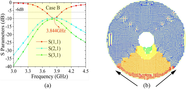
Figure 4 Case B – simulated S-parameters of Port 1 (a) and simulated surface current distribution of Port 1 at 3.844 GHz (b).
Case C adds the shorting pins to the conditions of Case A. This is the final structure. Since the shorting pins are placed along the zero point of the electric field in Case A, two different resonance modes are created when the pins are added. One is shown in Case A, where the basic mode of this circular patch antenna is TM1,1 mode. The other is a new TM1/2,1 resonant mode generated by the excitation of the shorting pins at 3.445 GHz (see Figure 5a).
The resonant frequencies are 3.445 and 4.046 GHz, and the – 6 dB impedance bandwidth covers the N77 band (3.3 to 4.2 GHz). By cutting out a circular slot in the middle of the antenna, isolation between diagonal elements is effectively increased.
Figures 5b and c show the two-dimensional vector current diagram of Antenna 1 at 3.445 GHz. Its resonant mode is stimulated with the shorting pins. The current direction within the fan patch flows from the edges of the shorting pins, which is because the pins divide it into the main patch and the parasitic patch. From the three-dimensional vector electric field distribution in Figure 5d, it is apparent that the antenna generates a pair of mirror TM1/2,1 resonant modes at 3.445 GHz.
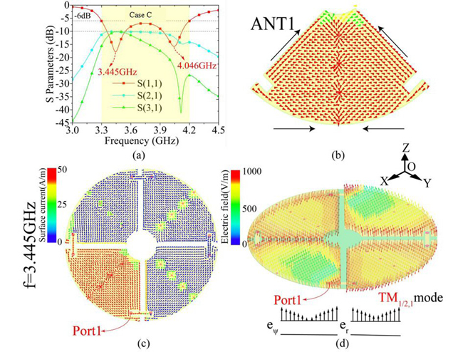
Figure 5 Case C – simulated S-parameters of Port 1 (a), simulated surface current distribution of Antenna 1 (b), simulated surface current distribution of Port 1 (c) and electric field distribution at 3.445 GHz (d).
At 4.046 GHz a three-eighth circular resonant patch is formed (see Figure 6). It is the resonant mode generated by Cases A and B together. The antenna generates two resonant modes, namely the TM11 mode and the TM1/2,1 mode. Note that the design adopts a microstrip line for coupled feeding. The microstrip line is used to connect antenna 1 and antenna 2.
As seen from the two-dimensional vector current diagram, the joint excitation of antennas 1 and 2 generates the resonant mode. The resonant TM1,1 mode is generated in antenna 1 due to the fundamental pattern produced by the quarter circular patch in Case A, while the resonant TM1/2,1 mode is generated in antenna 2. This is because of the half-mode patch TM1/2,1 mode from Case B due to the shorting pins.
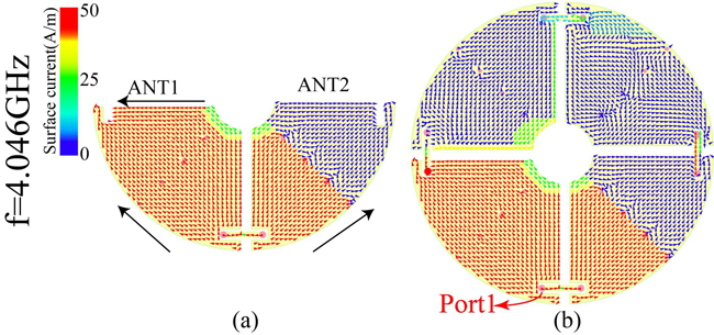
Figure 6 Simulated surface current distribution of Antenna 1 (a) and Port 1 (b) at 4.046 GHz.
RESULTS AND DISCUSSION
To verify the antenna design, a prototype is built and tested (see Figure 7). Due to welding errors, the difficulty in maintaining a 2 mm air layer and the relative flatness of the 0.4 mm dielectric substrate, there are some differences between measurement and simulation, but these differences are not substantial.
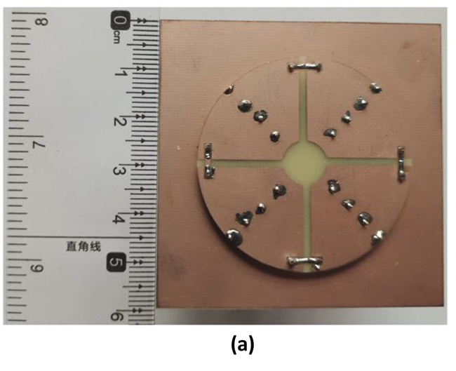
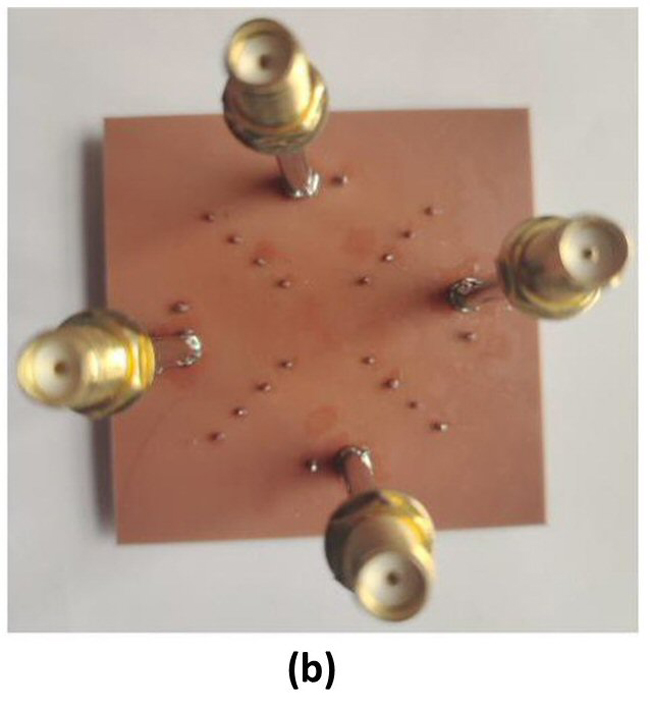
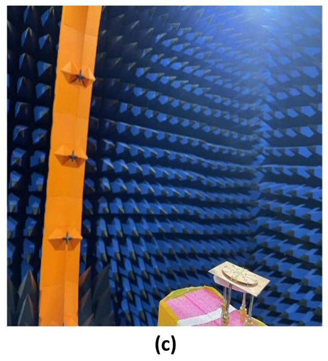
Figure 7 Fabricated prototype: top view (a), bottom view (b) and the antenna mounted in an anechoic chamber for testing (c).
Figure 8 shows the S-parameters, total efficiency and the envelope correlation coefficient (ECC) of the antenna simulation. From the S11 plot, the antenna's simulated – 6 dB impedance bandwidth is 900 MHz (3.30 to 4.20 GHz) providing coverage of the newly introduced N77 5G band (3.30 to 4.20 GHz). Isolation between adjacent and diagonal antenna elements is flat, and greater than 10 dB.
The range of total efficiency within the N77 band is 38 to 68 percent. Because the antenna is arrayed in a rotated grid and the elements are orthogonally polarized, the ECC is relatively small at less than 0.25 across the band.
Figure 9 shows the measured results. It is consistent with the simulations. At – 6 dB, the measured impedance bandwidth is slightly less than the simulated value, and isolation at greater than 10 dB is consistent with simulated results. The antenna efficiency is between 35 and 70 percent and the ECC is lower than 0.26.
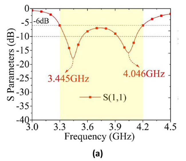
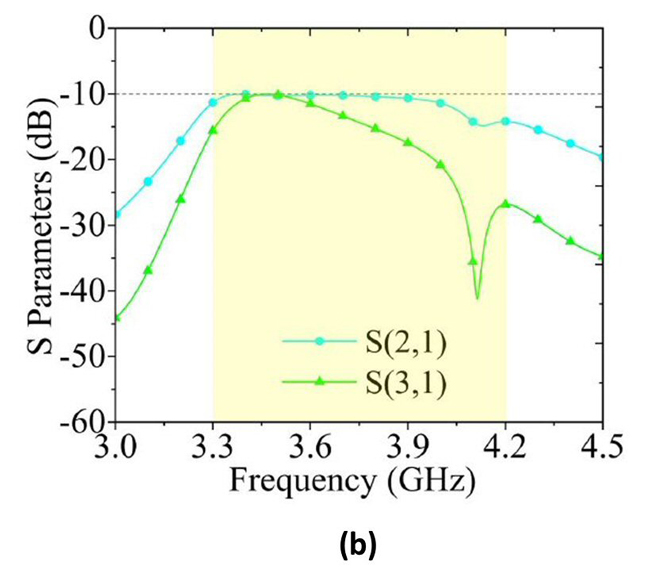
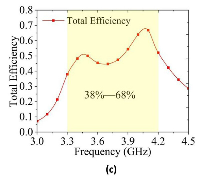
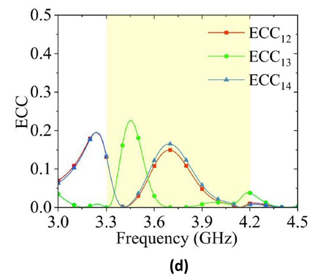
Figure 8 Simulated antenna reflection coefficient (a), mutual coupling (b), efficiency (c) and ECC (d).
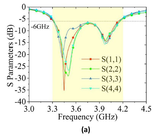
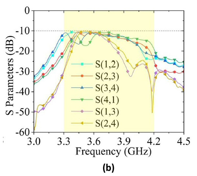
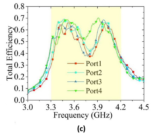
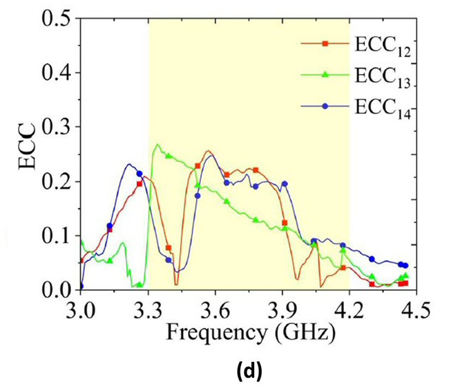
Figure 9 Colosseum block diagram.Measured antenna reflection coefficient (a), mutual coupling (b), efficiency (c) and ECC (d).
Figure 10 shows XoZ and YoZ radiation patterns at 3.445 and 4.046 GHz with Port 1 driven. Because the antenna is arrayed on a rotated grid, only the radiation patterns of Antenna 1 are shown. Note that when Φ=90 degrees, the Eθ component tilts to the direction of the wide side ACD (see Figure 2). Patterns for Antenna 1 through 4 tilt in four different directions, which promotes higher antenna isolation and lower ECCs.
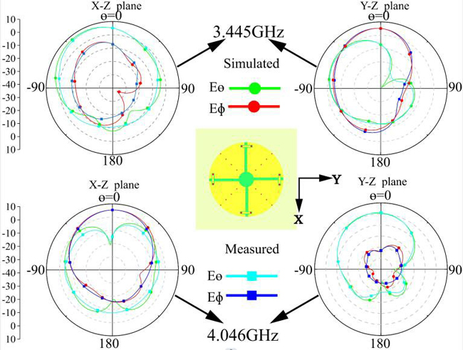
Figure 10 Measured and simulated radiation patterns of Antenna 1 driven at Port 1.
CONCLUSION
A low-profile four-port circular patch antenna provides a MIMO capability covering the 5G N77 band (3.3 to 4.2 GHz). Its application is 5G intelligent terminal equipment, especially for mounting on metal surfaces. Each port delivers wideband operation by merging two modes. The radius of the circular patch is 22 mm and the height is only 2.4 mm. This antenna’s structure and design process is outlined and prototype testing verifies its feasibility.
References
- L. Chang, Y. Yu, K. Wei and H. Wang, “Orthogonally Polarized Dual Antenna Pair With High Isolation and Balanced High Performance for 5G MIMO Smartphone,” IEEE Transactions on Antennas and Propagation, Vol. 68, No.5, May 2020, pp.3487-3495.
- X. -T. Yuan, W. He, K. -D. Hong, C. -Z. Han, Z. Chen and T. Yuan, “Ultra-Wideband MIMO Antenna System with High Element-Isolation for 5G Smartphone Application,” IEEE Access, Vol. 8, March 2020, pp. 56281-56289.
- L. Chang, Y. Yu, K. Wei and H. Wang, “Orthogonally Polarized Dual Antenna Pair with High Isolation and Balanced High Performance for 5G MIMO Smartphone,” IEEE Transactions on Antennas and Propagation, Vol. 68, No. 5, May 2020, pp. 3487-3495.
- L. Chang and H. Liu, “Low-Profile and Miniaturized Dual-Band Microstrip Patch Antenna for 5G Mobile Terminals,” IEEE Transactions on Antennas and Propagation, Vol. 70, No. 3, March 2022, pp. 2328-2333.
- Y. Gao, J. Wang, X. Wang and M. Wei, “A Low Profile Broadband Multimode Patch Antenna for 5G Mobile Applications,” IEEE Antennas and Wireless Propagation Letters, Vol. 22, No. 5, May 2023, pp. 1029-1024.
- Y. Gao, J. Wang, X. Wang and Z. Sun, “Extremely Low-Profile Dual-Band Antenna Based on Single-Layer Square Microstrip Patch for 5G Mobile Application,” IEEE Antennas and Wireless Propagation Letters, Vol. 22, No. 7, July 2023, pp. 1761-1765.
- V. Shanmugam Bhaskar and E. L. Tan, “Same-Sense Circularly Polarized Grid-Slotted Patch Antenna with Wide Axial Ratio Bandwidth,” IEEE Transactions on Antennas and Propagation, Vol. 70, No. 2, February 2022, pp. 1494-1498.
- K. -L. Wong and T. -W. Chiou, “Broadband Dual-Polarized Patch Antennas Fed by Capacitively Coupled Feed and Slot-Coupled Feed,” IEEE Transactions on Antennas and Propagation, Vol. 50, No. 3, March 2002, pp. 346-351.
- J. A. Liu, Y. F. Cao and X. Y. Zhang, “A Pattern-Reconfigurable Filtering Patch Antenna Using Embedded Resonators and Switchable Elements,” IEEE Transactions on Antennas and Propagation, Vol. 70, No. 5, May 2022, pp.3828-3833.
- C. -L. Mak, K. -M. Luk, K. -F. Lee and Y. -L. Chow, “Experimental Study of a Microstrip Patch Antenna with an L-Shaped Probe,” IEEE Transactions on Antennas and Propagation, Vol. 48, No. 5, May 2000, pp. 777-782.
- Y. -X. Guo, C. -L. Mak, K. -M. Luk and K. -F. Lee, “Analysis and Design of L-Probe Proximity Fed-Patch Antennas,” IEEE Transactions on Antennas and Propagation, Vol. 49, No. 2, February 2001, pp. 145-149.
- K. -R. Xiang, F. -C. Chen, Q. Tan and Q. -X. Chu, “High-Selectivity Filtering Patch Antennas Based on Multipath Coupling Structures,” IEEE Transactions on Microwave Theory and Techniques, Vol. 69, No. 4, April 2021, pp. 2201-2210.
- S. Radavaram, S. Naik and M. Pour, “Stably Polarized Wideband Circular Microstrip Antenna Excited in TM12 Mode,” IEEE Transactions on Antennas and Propagation, Vol. 69, No. 4, April 2021, pp. 2370-2375.
- C. -F. Liang, Y. -P. Lyu, D. Chen and C. -H. Cheng, “Wideband Circularly Polarized Stacked Patch Antenna Based on TM₁₁ and TM₁₀,” IEEE Transactions on Antennas and Propagation, Vol. 70, No. 4, April 2022, pp. 2459-2467.
- S. Wen and Y. Dong, “A Low-Profile Vertically Polarized Antenna with Conical Radiation Pattern for Indoor Micro Base Station Application,” IEEE Antennas and Wireless Propagation Letters, Vol. 20, No. 2, February 2021, pp. 169-173.
- X. Zhang, K. -D. Hong, L. Zhu, X. -K. Bi and T. Yuan, “Wideband Differentially Fed Patch Antennas Under Dual High-Order Modes for Stable High Gain,” IEEE Transactions on Antennas and Propagation, Vol. 69, No. 1, January 2021, pp. 508-513.
- N. -W. Liu, L. Zhu and W. -W. Choi, “A Differential-Fed Microstrip Patch Antenna with Bandwidth Enhancement Under Operation of TM10 and TM30 Modes,” IEEE Transactions on Antennas and Propagation, Vol. 65, No. 4, April 2017, pp.1607-1614.
- L. Chang and H. Wang, “Dual-Band Four-Antenna Module Covering N78/N79 Based on PIFAfor 5G Terminals,” IEEE Antennas and Wireless Propagation Letters, Vol. 21, No. 1, January 2022, pp. 168-172.
- D. Sarkar and K. V. Srivastava, “A Compact Four-Element MIMO/Diversity Antenna with Enhanced Bandwidth,” IEEE Antennas and Wireless Propagation Letters, Vol. 16, July 2017, pp. 2469-2472.
- K. -L. Wong, M. -F. Jian, C. -J. Chen and J. -Z. Chen, “Two-Port Same-Polarized Patch Antenna Based on Two Out-of-Phase TM10 Modes for Access-Point MIMO Antenna Application,” IEEE Antennas and Wireless Propagation Letters, Vol. 20, No. 4, April 2021, pp. 572-576.
- B. Cheng and Z. Du, “Dual Polarization MIMO Antenna for 5G Mobile Phone Applications,” IEEE Transactions on Antennas and Propagation, Vol. 69, No. 7, July 2021, pp. 4160-4165.
- K. -L. Wong and G. -L. Yan, “Wideband Three-Port Equilateral Triangular Patch Antenna Generating Three Uncorrelated Waves for 5G MIMOAccess Points,” IEEE Access, Vol. 10, December 2021, pp. 893-899.
- K. -L. Wong, H. -J. Chang, J. -Z. Chen and K. -Y. Wang, “Three Wideband Monopolar Patch Antennas in a Y-Shape Structure for 5G Multi-Input–Multi-Output Access Points,” IEEE Antennas and Wireless Propagation Letters, Vol. 19, No. 3, March 2020, pp. 393-397.
- K. -L. Wong, C. -M. Chou, Y. -J. Yang and K. -Y. Wang, “Multipolarized Wideband Circular Patch Antenna for Fifth-Generation Multi-Input-Multi-Output Access-Point Application,” IEEE Antennas and Wireless Propagation Letters, Vol. 18, No. 10, October 2019, pp. 2184-2188.
- K. -L. Wong, X. -Q. Ye and W. -Y. Li, “Wideband Four-Port Single-Patch Antenna Based on the Quasi-TM1/2,1/2 Mode for 5G MIMO Access-Point Application,” IEEE Access, Vol. 10, January 2022, pp. 9232-9240.
- K. -L. Wong, J. -Z. Chen and W. -Y. Li, “Four-Port Wideband Annular-Ring Patch Antenna Generating Four Decoupled Waves for 5G Multi-Input-Multi-Output Access Points,” IEEE Transactions on Antennas and Propagation, Vol. 69, No. 5, May 2021, pp. 2946-2951.
- L. Chang and H. Wang, “Miniaturized Wideband Four-Antenna Module Based on Dual-Mode PIFA for 5G 4 ×4 MIMO Applications,” IEEE Transactions on Antennas and Propagation, Vol. 69, No. 9, September 2021, pp. 5297-5304.
- K. -L. Wong, M. -F. Jian and W. -Y. Li, “Low-Profile Wideband Four-Corner-Fed Square Patch Antenna for 5G MIMO Mobile Antenna Application,” IEEE Antennas and Wireless Propagation Letters, Vol. 20, No. 12, December 2021, pp. 2554-2558.
- I. Barani, K. Wong, Y. Zhang and W. Li, “Low-Profile Wideband Conjoined Open-Slot Antennas Fed by Grounded Coplanar Waveguides for 4×4 5G MIMO Operation,” IEEE Transactions on Antennas and Propagation, Vol. 68, No. 4, April 2020, pp. 2646-2657.