
Design of a Tri-Band Microstrip Bandpass Filter with High Performance for 5G Applications
A tri-band microstrip bandpass filter is designed for 5G applications. It uses multi-mode stepped-impedance resonators (MSIRs) and open loop ring resonators (OLRRs). By controlling the impedance ratio and electric length of the MSIRs, higher resonant modes are suppressed out of band. The meander OLRRs produce two extra transmission zeros in the upper and lower sides of the second passband that provide good isolation between passbands. A high performance passband response is demonstrated with a small shape factor and low insertion loss. Measured results show good agreement with simulation.
With the rapid development of modern wireless communication systems, the multi-band filter has become a critical circuit component for versatile 5G applications. Much work has been done on the design of multi-band filters with low loss and high selectivity.1-3
There are several approaches. In the work of Tsai and Hsue,4 a bandpass filter (BPF) and a bandstop filter were cascaded to realize a dual-band BPF. It results in a large circuit size, however, and requires additional external matching networks as well. The use of OLRRs and stub-loaded OLRRs5,6 is a simple and effective method for multi-band filter design. Unfortunately, higher-order modes are easily excited. Stepped-impedance resonators (SIRs), characterized by controlling higher-order modes conveniently, are also typically used;7-9 however, poor isolation between passbands and complexity are major disadvantages.
In this work, a novel tri-band microstrip BPF is designed based on a simple and effective method. The filter comprises two open-end microstrip lines, a pair of MSIRs and two pairs of OLRRs (see Figure 1). The MSIRs tune the higher-order modes and higher-order upper stopband. The meander OLRRs, provide greater skirt selectivity with two extra transmission zeros.

Figure 1 Tri-band filter schematic layout.

Figure 2 MSIR structure (a), even-mode equivalent circuit (b) and odd-mode equivalent circuit (c).
RESONATOR ANALYSIS
The OLRRs and meander OLRRs have been analyzed by Hong,10 therefore, only the MSIRs will be reviewed theoretically here. Figure 2a shows the MSIR structure. Even-odd mode analysis can be used due to its symmetry. Figure 2b is the even mode equivalent circuit and Figure 2c is the odd mode equivalent circuit.
The input admittances for even and odd modes can be expressed by Equations (1) and (5).
Here, l1, l2, l3, l4 and l5 are the lengths of each stub with impedances z1, z2, z3, z4 and z5. The corresponding electrical lengths of the stubs are θ1 = β1l1, θ2 = β2l2, θ3 = β3l3, θ4 = β4l4 and θ5 = β5l5. The impedance ratio k1 = z2/z1 and k2 = z3/z1. The resonant condition of the MSIRs is when the input admittance equals zero, namely, Ye = Yo = 0. Then:

As shown in Figure 3, the first even mode (f1even) and the first odd mode (f1odd) resonant frequencies can be tuned by changing the impedance ratio k1. The impedance ratio k2 mainly influences the second even mode (f2even). Figure 4 shows that f1even and f2even also depend on the lengths of l3 and l5, respectively. The resonator can then be determined by properly choosing these parameters.

Figure 3 Operating frequencies as a function of impedance ratios k1 (a) and k2 (b).
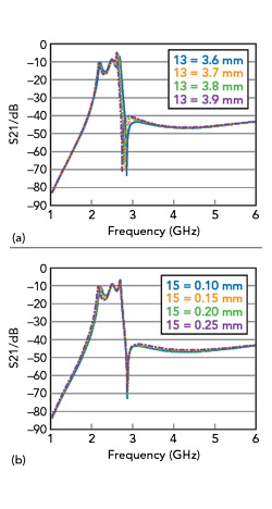
Figure 4 Operating frequencies as a function of lengths l3 (a) and l5 (b).
TRI-BAND BPF DESIGN
Based on the theory of MSIRs, the tri-band BPF centered at 2.4, 4 and 5.6 GHz is designed (see Figure 1). It comprises two open-end feed lines, a pair of MSIRs and two pairs of OLRRs. The MSIRs determine the first passband center frequency, fractional bandwidth and selectivity. The chosen parameters are: k1= 0.75, k2 = 0.3, l1 = 7.6 mm, l2 = 3.93 mm, l3 = 3.6 mm, l4 = 3.24 mm, l5 = 0.1 mm, w1 = 0.195 mm, w2 = 0.4 mm and w3 = 1.8 mm.
The OLRRs are traditional half wavelength resonators determining the second and third passband responses. The difference is that the OLRRs used in the second passband are meandered. Two extra transmission zeros are produced between the first and second and the second and third passbands. This improves passband isolation and selectivity.
The bandwidths depend on the coupling coefficients and external quality factors. That is, s1, s2, d1 and d2 affect the bandwidths; s1 = 0.4, s2 = 0.6, d1 = 0.1 and d2 = 0.2 mm. The length L of the open-end feed line is about a half wavelength at the first operating frequency of 2.4 GHz and the impedance is 50 Ω. Here L = 30 and w = 0.5 mm.
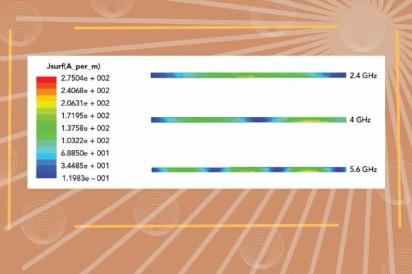
Figure 5 shows the current distribution of the feed line at 2.4, 4 and 5.6 GHz. The resonators are placed at positions of maximal current distribution for strong magnetic coupling.

Figure 5 Current distribution of open-ended feed line.
The filter is fabricated on a substrate with a relative permittivity of 9.6 with a dielectric height of 0.5 mm. The overall size of the filter is 30 × 9 mm.
RESULTS AND DISCUSSION
The tri-band BPF (see Figure 6) is simulated using ADS Momentum and measured using a Keysight 8719ES network analyzer (see Figure 7). Measured results show good agreement with the simulation. The passbands are centered at 2.4, 4 and 5.6 GHz with 3 dB bandwidths of 5.9, 44 and 22.4 percent, respectively, with insertion loss less than 1.1, 0.8 and 0.1 dB. The locations of transmission zeros are at 2.72, 3.2, 3.68, 4.35, 4.8 and 6.6 GHz, providing rejection greater than 35 dB.

Figure 6 Tri-band BPF photograph.
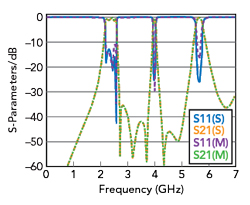
Figure 7 Tri-band BPF simulation and measurements.
Table 1 compares this performance with other work, showing that this filter contains the most transmission zeros and the best isolation between passbands.

CONCLUSION
A novel tri-band BPF combines MSIRs and OLRRs. The proper impedance ratios and electrical lengths of the MSIRs realize a wide upper stopband. The meander OLRRs produce two extra transmission zeros at the upper and lower sides of the second passband, which improves band-to-band rejection. Consequently, the low-cost tri-band BPF is only 30 × 9 mm2 with operating frequencies at 2.4, 4 and 5.6 GHz. The insertion loss of each band is less than 1.1 dB and band-to-band rejection is better than 35 dB. High selectivity, compact size and low insertion loss makes it attractive for use in 5G applications.
References
- B. Ren, Z. Ma, H. Liu, X. Guan, P. Wen and M. Ohira, “Compact Multi-Band Differential Bandpass Filters Using Microstrip Multi-Mode Resonators,” IEEE MTT-S International Wireless Symposium, May 2019.
- V. N. Rahangdale and J. Sengupta, “Stub-Loaded Resonators Application in Ultra Compact Multi-Band Bandpass Filter,” 9th International Conference on Computing, Communication and Networking Technologies, July 2018.
- H. Liu, R. Wang, C. Lai, H. Li and Z. Zuo, “A Compact Quint-Band Bandpass Filter with High Selectivity Using Uniform Impedance Resonators,” IEEE MTT-S International Microwave Workshop Series on Advanced Materials and Processes for RF and THz Applications, July 2020.
- L. -C. Tsai and C. -W. Hsue, “Dual-Band Bandpass Filters Using Equal-Length Coupled-Serial-Shunted Lines and Z-Transform Technique,” IEEE Transactions on Microwave Theory and Techniques, Vol. 52, No. 4, April 2004, pp. 1111–1117.
- C. -Y. Chen and C. -Y. Hsu, “A Simple and Effective Method for Microstrip Dual-Band Filters Design,” IEEE Microwave and Wireless Components Letters, Vol. 16, No. 5, May 2006, pp. 246-248.
- X. Lai, B. Wu, T. Su and C. -H. Liang, “A Novel Tri-Band Filter Using Stub-Loaded Open Loop Ring Resonators,” Microwave and Optical Technology Letters, Vol. 52, No. 3, March 2010, pp. 523–526.
- C. -F. Chen, “Design of a Compact Microstrip Quint-Band Filter Based on the Tri-Mode Stub-Loaded Stepped-Impedance Resonators,” IEEE Microwave and Wireless Components Letters, Vol. 22, No. 7, July 2012, pp. 357–359.
- A. Neogi and J. R. Panda, “Dual-Band Filter with Centrally Loaded SIR and DGS for WLAN Applications,” 4th International Conference on Electronics, Communication and Aerospace Technology, November 2020.
- C. Chen, T. Shen, T. Huang and R. Wu, “Design of Multimode Net-Type Resonators and Their Applications to Filters and Multiplexers,” IEEE Transactions on Microwave Theory and Techniques, Vol. 59, No. 4, April 2011, pp. 848–856.
- J. S. Hong, Microstrip Filters for RF/Microwave Applications, Second Edition, Wiley, 2011.
- B. A. Kumar and O. P. Meena, “Design & Simulation of a Compact Multi-Band Microstrip Bandpass Filter using C shaped Stub-Loaded Resonators,” IEEE Students Conference on Engineering & Systems, July 2020.
- S. Lan, M. Weng, S. Chang, C. Hung and S. Liu, “A Tri-Band Bandpass Filter with Wide Stopband Using Asymmetric Stub-Loaded Resonators,” IEEE Microwave and Wireless Components Letters, Vol. 25, No. 1, January 2015, pp. 19–21.