

Online Spotlight: A Comprehensive Survey of Ultra-Wideband Dielectric Resonator Antennas
Techniques, geometries, fabrication technologies and materials with ultra-wideband (UWB) characteristics for dielectric resonator antennas (DRA) are discussed. DRAs are placed on ground planes or dielectric substrates (rigid or flexible) and excited by different feed mechanisms. With the development of rectangular, cylindrical and other geometries, the fundamental goals are electrical size miniaturization, greater bandwidth to meet commercial requirements and radiation pattern stability. The focus is on applications related to portable devices, handheld devices, radio base stations, radar and satellite communication. The novel 'OM'-shaped air-spaced DRA, cross-shaped parasitic strip-based MIMO rectangular DRA and rack-shaped MIMO DRA for UWB applications are also addressed.
Compact UWB antennas have recently been investigated for wireless communication systems. In 2002, the Federal Communications Commission (FCC) allowed a UWB range of unlicensed bands from 3.1 to 10.6 GHz.1 For a UWB system, a broadband antenna is required. The challenges of UWB antenna design include impedance matching, compactness (size), radiation stability and low cost. Several types of UWB antennas were proposed.2,3
Since the development of low-loss ceramics in the 1960s, dielectric resonators (DRs) have been used in microwave circuit applications.4-6 Early research to determine the resonant frequencies of DRs resulted in advances in the design of antennas utilizing such resonators as antennas. The DRA has attracted much attention over the last two decades because of its many attractive features such as low profile, high radiation efficiency, low conductor loss, light weight, ease of fabrication and low cost.7-10
DRAs are available in various forms, such as: rectangular, cylindrical, triangular, L-shaped, conical, T-shaped, trapezoidal, A-shaped, E-shaped, P-shaped, C-shaped, F-shaped, H-shaped U-shaped, V-shaped, Z-shaped and super-shaped.11-25 Size and bandwidth are controlled by changing the material permeability (εDR). Being a 3D radiating structure, it enjoys greater design flexibility and adaptability than conventional antennas.
Short-range communication operates in a rich scattering environment, which can cause fading due to multipath, power loss due to disintegrating conditions or mismatches due to transmitter-receiver antenna orientation.26 A DRA can easily produce circular polarization characteristics through various techniques such as: shape modification, metallic strips, cross-slot-coupling and single/dual feeding structures.27-30
In recent years, there has been an increasing demand for MIMO antennas with high data rates, high reliability, high channel capacity, low channel interference and low envelope correlation coefficient (ECC).31-34 MIMO DRAs can be categorized by single or multiple radiator elements. A two DR radiator element was chosen in the MIMO system described by Das et al.35 MIMO diversity parameters such as ECC, mean effective gain and total active reflection coefficient were calculated.35
DRAs are used in various configurations to provide significant improvements in bandwidth, radiation efficiency and gain as well as reduced antenna size. The number of papers related to UWB DRAs published between 2005 to 2021 (see Figure 1) shows an increasing interest in this area.

Figure 1 UWB DRA papers published per year.
The most common DRA shapes are cylindrical, rectangular and hemispherical. DRA resonant mode excitation depends upon input excitation, cavity volume and boundary conditions. Standing waves are generated based on these parameters at resonance. The standing waves are converted into traveling waves due to transparent walls (boundary conditions). Resonant modes such as TE, TM, TEM, HE and HEM can be excited. These are also known as transverse electric, transverse magnetic and hybrid modes. Fundamental or higher order modes can be excited, such as (TE111–TElmn) and (TM111–TMlmn).10 UWB performance can be achieved through mode merging. Modified shapes and the use of defective ground structures (DGS), stubs and other techniques are also used to enhance antenna performance.
The following sections describe some of the techniques used to design UWB DRAs. Examples are also presented, addressing their advantages and disadvantages.
UWB DRA BASED ON A THIN MONOPOLE
A monopole-loaded single annular ring DRA with the same axial reference was designed for UWB applications by Lapierre et al.36 The cylindrical DR was set on a finite ground plane and excited by a probe fed with a quarter-wave monopole (see Figure 2). Prototype Antenna #1 covered a frequency range between 6.3 and 16.2 GHz with Εr1 = 10 and L = 10 mm. Prototype Antenna #2 covered a frequency range between 4.2 and 10.1 GHz with Εr2 = 20 and L = 15 mm. Results for several other monopole DRAs have also been reported.37-48

Figure 2 Single annular ring DRA.36
UWB ELECTROMAGNETICALLY COUPLED DRA
Denidni and Weng49 introduced a new rectangular-shaped DRA (RDRA) for UWB applications. The RDRA comprised a DR excited by a bevel-shaped patch coaxial feed, providing an air gap between the DR and the infinite ground plane (see Figure 3). The 27.2 × 12.6 × 19.1 mm3 RDR made of Rogers TMM 10i was mounted on a 75 × 90 mm2 ground plane. The Q-factor and effective permittivity were reduced by the air gap and bevel-shaped feed, providing mode transition and the widening bandwidth. Radiation efficiency of the antenna in the operating band was greater than 90 percent. Its reported impedance bandwidth was 120 percent (2.6 to 11 GHz). Many other authors have also published electromagnetically coupled DRAs for UWB operation.50-52
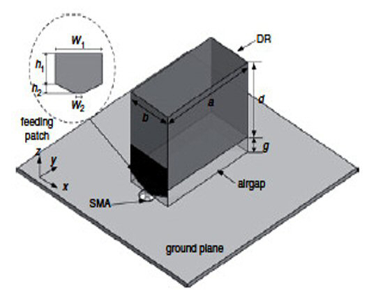
Figure 3 Rectangular DRA with the air gap.49
UWB PATCH-BASED DRA
Aoutoul et al.53 investigated a compact RDRA with permittivity εr= 10.2 with a low profile substrate of permittivity εr=3 and modified ground. The 10 × 10 × 2.5 mm3 RDR sat on a 30 × 45 ×1.27 mm3 substrate. The dimensions of the truncated ground plane were 30 × 25 mm2 (see Figure 4). A 3.94 × 3.94 × 1.2 mm3 metallic layer was placed beneath the DRA to improve its bandwidth (31 percent, 6.86 to 9.41 GHz) and impedance matching. An impedance bandwidth of 46 percent (6.9 to 11 GHz) was achieved using a stepped slot in the ground plane. Other patch-based DRA designs developed for UWB applications have been reported.54-57

Figure 4 Compact RDRA.53
UWB INSERTED DRA
Ryu and Kishk58 described a novel portable DRA for UWB wireless applications. The antenna provided a broadside radiation pattern using a solid RDR mounted on the edge of a vertical ground plane. The total size of the DRA was 18.3 × 14 × 5.08 mm3. It had a 10.2 permittivity and was bonded to an RT6002 substrate. Its impedance bandwidth was 84 percent. A wide impedance bandwidth (93 percent from 3.5 to 9.6 GHz) was obtained with a modified version of the RDR, which consisted of two dielectric fragments configured into an A-shape (see Figure 5). Similar structures have been reported by other researchers.59

Figure 5 A-Shaped DRA with modified ground.58
UWB DRA WITH BAND REJECTION CHARACTERISTICS
Sabouni et al.60 proposed an A-shaped DRA for UWB applications. The radiating element was excited by a transformer type of microstrip feed printed on the substrate. It covered 3.5 to 10.5 GHz, which supports the UWB range. Shorted stubs produced the notch features of the antenna. These elements were parasitically coupled to the feedline (see Figure 6). Two notches were created in the UWB when two U-shaped parasitic elements were used with lengths of 8.96 and 10.65 mm, and a width of 1 mm. The peak gain of the antenna was 5.46 dB without a notch. UWB DRAs with band notch characteristics have been investigated by several researchers.61-63

Figure 6 A-shaped DRA with U-shaped parasitic elements.60
UWB STACKED OR SEGMENTED OR COMPOSITE DRA
Ge et al.64 designed a rectangular DRA for UWB operation. The RDRA exploited multiple low-Q modes with overlapping bandwidths to achieve a wide contiguous bandwidth. This was achieved using a full-length, low permittivity, insert between a higher permittivity dielectric volume and a ground plane (see Figure 7a). The volume of the DR was reduced with a finite conducting wall fixed on the side of the DR layer. The impedance bandwidth of the DRA was 110 percent from 3.1 to 10.7 GHz.
Kshirsagar et al.65 proposed a two-segment RDRA combination of half-size RDRAs made up of materials placed side-by-side with εr= 4.3 and εr= 9.2 and excited by a common microstrip feed (see Figure 7b). The effect of a defected ground was also investigated. A parametric study of the DGS angle was conducted at 0, 30 and 45 degrees. The antenna covered the UWB at an angle of 45 degrees from 2.9 to 11.6 GHz (120 percent bandwidth). The antenna exhibited a peak gain of 7.2 dBi. Many authors have used this same concept for enhancing the antenna characteristics.66–70

Figure 7 Stacked DRA with LPI64 (a) and RDRA based on a patch or conformal strip65 (b).
UWB RECONFIGURABLE DRA
Abioghli et al.71 developed a reconfigurable DRA antenna, with dimensions 40 × 40 × 7.3 mm3. The ground plane was constructed by connecting an L-shaped stub and cutting two slots. It used a T-shaped DR of Rogers RT6010 with relative permittivity εr= 10.2 placed on a 1.6 mm thick FR4 substrate (see Figure 8). Reconfigurability was achieved with a PIN diode that modified the current distribution path in the ground. The diodes were biased at 0.7 V and a suitable impedance match was provided for the 17 mm ground length. Further work by Abioghli et al.72 on narrow band reconfigurable DRAs for cognitive radio application has been reported.
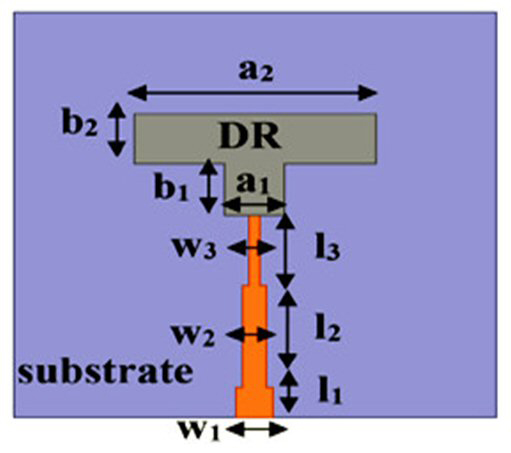
Figure 8 T-shaped reconfigurable DRA.71
OTHER UWB DR SHAPES
Sankaranarayanan et al.73 proposed a unique and compact modified Koch snowflake DRA geometry for broadband use. The radius and height of the cylindrically shaped DRA (CDRA) were 2.68 and 1.5 cm, respectively. An FR4 substrate was used with a ground plane of 10 × 10 cm2. Initially, a Koch snowflake design was developed on a basic CDRA (see Figure 9); however, a fractal ring structure was used to increase the overall impedance bandwidth and gain. The DRA covered the microwave frequency band from 4.7 to 12.4 GHz for a 90 percent bandwidth. Furthermore, the final geometry yielded a 76.6 percent reduction in DRA size. It had a 78 percent radiation efficiency across the entire impedance bandwidth with a maximum gain of 8.76 dBi. Other DRA shapes, such as bi-cone shaped, laterally fixed cylindrical, Turtle-shaped, T-shaped and E-shaped have also been investigated.74-80
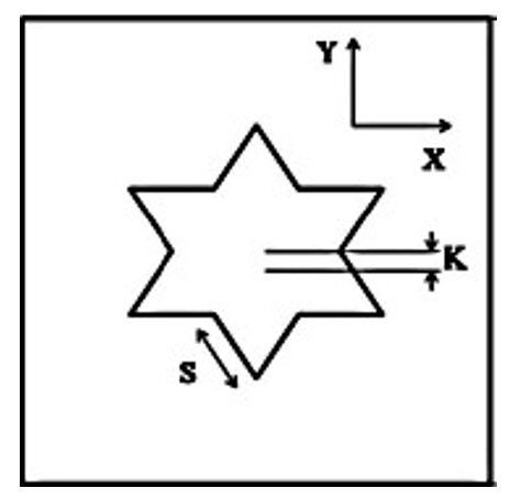
Figure 9 Modified Koch snowflake DRA.73
A proposed rectangular DRA designed for UWB applications is shown in Figure 10.80 It comprised a cylindrical air gap based RDRA, modified ground plane and metallic strips on a Rogers 5880 substrate. A cylindrical DR (CDR) with a diameter of 2xD1 enhanced its gain and bandwidth, and metallic strips improve its impedance characteristics. The antenna's near field supported dominant, second and third-order TE modes for a wide 103.9 percent impedance bandwidth covering the frequency range from 3.28 to 10.4 GHz.

Figure 10 Air-spaced RDRA (a) with modified ground (b).80
ELLIPTICALLY OR CIRCULARLY POLARIZED UWB DRA
Haraz et al.81 described a half-cylindrical DRA (HCDRA) with CP characteristics for UWB applications. The HCDR was mounted on a finite ground plane on the bottom side of the substrate (see Figure 11a). The impedance bandwidth of the antenna was 90 percent covering the frequency range from 4 to 10.5 GHz. It exhibited an axial ratio bandwidth of 27 percent from 5.3 to 7 GHz.
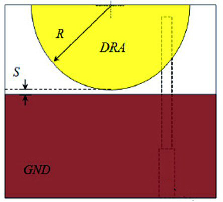
Figure 11a Half-cylindrical CP DRA81
Chakraborty et al.82 described a dual-band antenna covering 3.7 to 4.4 GHz (17.28 percent bandwidth) and 5.8 to 6.2 GHz (11.56 percent bandwidth). It consisted of a pair of symmetrically positioned DRs on a flat I-shaped monopole. The fundamental modes were excited at 3.8 and 6 GHz to generate CP with the DRs placed orthogonally on the substrate (see Figure 11b).

Figure 11b DRA with symmetrically positioned DRs82
Yadav et al.83 achieved UWB performance with an OM-shaped DRA and DGS (see Figure 11c).83 It covered a frequency range from 3.1 to 11.1 GHz with a peak gain of 7.68 dB and reported a band from 6 to 11.1 GHz with elliptical polarization characteristics.
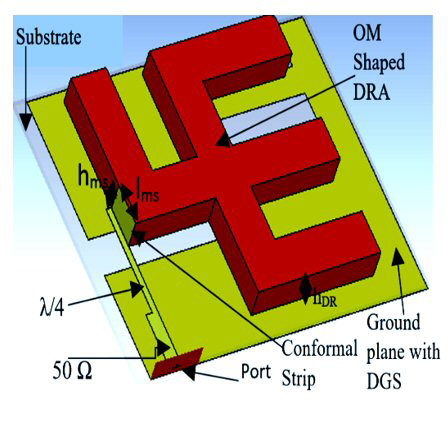
Figure 11c OM-shaped DRA with DGS83
UWB MIMO DRA
Abedian et al.84 designed a WLAN band rejection MIMO DRA. It was compact with dimensions of 29 × 29 × 5 mm3 and utilized a Taconic-35 substrate (see Figure 12a). A ground stub was used to improve isolation as well as impedance matching, and two L-shaped parasitic strips created a notch in the WLAN band from 5.15 to 5.85 GHz. The length and width of the strips could be adjusted to create a notch from 4.98 to 6.08 GHz. The compact DRA provided a broadside radiation and an impedance bandwidth of 106 percent (3.29 to 10.74 GHz), high radiation efficiency, and an ECC < 0.16.
Yadav et al.85 proposed a rack-shaped DRA with an inverted T-shaped parasitic strip designed for UWB applications. This MIMO antenna consisted of two radiators, a partial ground, stub and parasitic strip (see Figure 12b). Two DRA designs (one with and one without a parasitic strip) demonstrated impedance bandwidths of 72.67 percent (4.8 to 10.28 GHz) and 101.87 percent (3.54 to 10.89 GHz) with isolations greater than 21 and 15.6 dB, respectively. Reported diversity parameters were: directive gain (DG) ≥ 9.93 dB, TARC, group delay, ECC ≤ 0.0059 and channel capacity loss within the limits.
Sani et al.86 presented a stair-shaped rectangular DRA for UWB applications. The measured input impedance bandwidth of the antenna was 153.6 percent (1.6 to 12.2 GHz) with a minimum of 25 dB isolation between the radiators in the operating band. It demonstrated a low ECC and low mutual coupling throughout the desired frequency range.
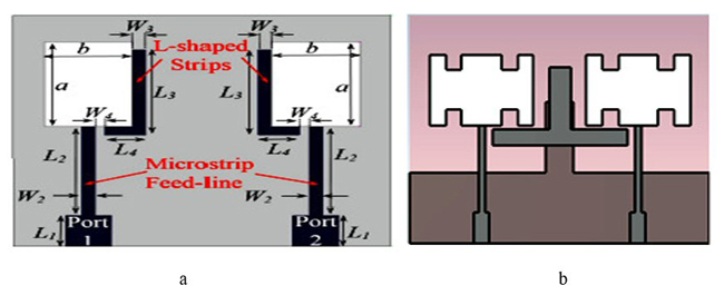
Figure 12 (a) Two-port MIMO DRA loaded with L-shaped strip84 (b) rack-shaped MIMO DRA with inverted T-shaped strip85
A two-radiator, element-based, MIMO with cross-shaped metallic parasitic strips (MPS) and an inverted T-shaped parasitic strip were designed for improved isolation as well as impedance bandwidth for UWB.87 The antenna consisted of two DRs, a partial ground with a scissor-shaped DGS, stub and parasitic strip (see Figure 13). Its impedance bandwidth of 104.6 percent covered the frequency band from 3.3 to 10.8 GHz. A cross-shaped metallic strip placed on the RDRA improved isolation, which was greater than 20 dB within the band. Its reported DG was 9.98 dB and ECC was 0.0059.
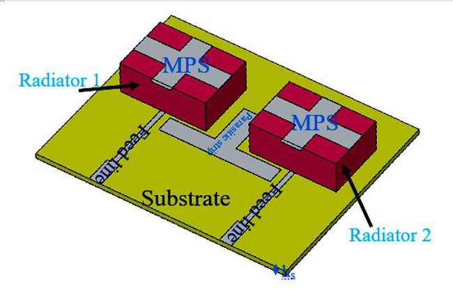
Figure 13 RDRA loaded with cross-shaped MPS.87
CONCLUSION
The basic geometries of DRAs are rectangular, cylindrical and hemispherical. Various shapes of DRs, DGS, modified grounds, parasitic elements, stubs, arrays and other techniques are used in the examples discussed to achieve UWB performance.
References
1. Revision of Part 15 of the Commission's Rules Regarding Ultra-Wideband Transmission Systems, FCC 02-48, Federal Communications Commission, 2002.
2. R. S. Kshetrimayum, “An Introduction to UWB Communication Systems," IEEE Potentials, Vol. 28, No. 2, March-April 2009, pp. 9-13.
3. Z. Guo, H. Tian, X. Wang, Q. Luo and Y. Ji, “Bandwidth Enhancement of Monopole UWB Antenna with New Slots and EBG Structures,” IEEE Antennas and Wireless Propagation Letters, Vol. 12, November 2013, pp.1550-1553.
4. M. K. Shrivastava, A. K. Gautam and B. K. Kanaujia, “An M‐Shaped Monopole‐Like Slot UWB Antenna,” Microwave and Optical Technology Letters, Vol. 56, No. 1, November 2013, pp. 127-131.
5. J. K. Plourde and C. -L. Ren, “Application of Dielectric Resonators in Microwave Components,” IEEE Transactions on Microwave Theory and Techniques, Vol. 29, No. 8, August 1981, pp. 754-770.
6. S. J. Fiedziuszko and S. Holmes, “Dielectric Resonators Raise your High-Q,” IEEE Microwave Magazine, Vol. 2, No. 3, September 2001, pp. 50-60.
7. C. Wang and K. A. Zaki, “Dielectric Resonators and Filters,” IEEE Microwave Magazine, Vol. 8, No. 5, October 2007, pp. 115-127.
8. K.M. Luk and K.W. Leung, Dielectric Resonator Antennas Handbook, Hertfordshire: Baldock, 2003.
9. A. Petosa, Dielectric Resonator Antenna Handbook, Artech House, 2007.
10. R.S. Yaduvanshi and H. Parthasarathy, Rectangular Dielectric Resonator Antennas, Springer, 2016.
11. M. W. McAllister, S. A. Long and G. L. Conway, “Rectangular Dielectric Resonator Antenna,” Electronics Letters, Vol. 19, No. 6, March 1983, pp. 218-219.
12. R. K. Mongia and A. Ittipiboon, “Theoretical and Experimental Investigations on Rectangular Dielectric Resonator Antennas,” IEEE Transactions on Antennas and Propagation, Vol. 45, No. 9, September 1997, pp. 1348-1356.
13. G. P. Junker, A. A. Kishk, A. W. Glisson and D. Kajfez, “Effect of Air Gap on Cylindrical Dielectric Resonator Antenna Operating in TM/Sub 01/Mode,” Electronics Letters, Vol. 30, No. 2, January 1994, pp. 97-98.
14. D. Guha and Y. M. M. Antar, “Four-Element Cylindrical Dielectric Resonator Antenna for Wideband Monopole-Like Radiation,” IEEE Transactions on Antennas and Propagation, Vol. 54, No. 9, September 2006, pp. 2657-2662.
15. K. Trivedi and D. Pujara, “Design and Development of Ultrawideband‐Stacked Triangular Prism‐Shaped Dielectric Resonator Antenna,” Microwave and Optical Technology Letters, Vol. 61, No. 5, May 2019, pp. 1193-1199.
16. T. A. Denidni, Q. Rao and A. R. Sebak, “Broadband L-Shaped Dielectric Resonator Antenna,” IEEE Antennas and Wireless Propagation Letters, Vol. 4, December 2005, pp. 453-454.
17. S. K. K. Dash, T. Khan and B. K. Kanaujia, “Conical Dielectric Resonator Antenna with Improved Gain and Bandwidth for X-Band Applications,” International Journal of Microwave and Wireless Technologies, Vol. 9, No. 8, October 2017, pp. 1749-1756.
18. A. Sharma, A. Sarkar, A. Biswas and M. J. Akhtar, “A‐Shaped Wideband Dielectric Resonator Antenna for Wireless Communication Systems and its MIMO Implementation,” International Journal of RF and Microwave Computer‐Aided Engineering, Vol. 28, No. 8, October 2018.
19. S. Danesh, M. R. Kamarudin, T. H. Rahman, M. Abedian, M. H. Jamaluddin and M. Khalily, “A C‐Shaped Dielectric Resonator Antenna with Frequency Reconfigurable for ISM and LTE Band Applications,” Microwave and Optical Technology Letters, Vol. 59, No. 1, November 2016, pp. 134-138.
20. S. F. Roslan, M. R. Kamarudin, M. Khalily and M. H. Jamaluddin, “An MIMO F‐Shaped Dielectric Resonator Antenna for 4G Applications,” Microwave and Optical Technology Letters, Vol. 57, No. 12, January 2015, pp. 2931-2936.
21. X. -L. Liang and T. A. Denidni, “H-Shaped Dielectric Resonator Antenna for Wideband Applications,” IEEE Antennas and Wireless Propagation Letters, Vol. 7, April 2008, pp. 163-166.
22. M. Khalily, M. Rahim, A. Kishk and S. Danesh, “Wideband P-Shaped Dielectric Resonator Antenna,” Radioengineering, Vol. 22, No. 1, April 2013, pp. 281-285.
23. X. -L. Liang and T. A. Denidni, “Cross-T-Shaped Dielectric Resonator Antenna for Wideband Applications,” Electronics Letters, Vol. 44, No. 20, October 2008, pp. 1176-1177.
24. L. -N. Zhang, S. -S. Zhong and S. -Q. Xu, “Broadband U-Shaped Dielectric Resonator Antenna with Elliptical Patch Feed,” Electronics Letters, Vol. 44, No. 16, February 2008, pp. 947-949.
25. S. S. Singhwal, B. K. Kanaujia, A. Singh and J. Kishor, “Circularly Polarized V‐Shaped Dielectric Resonator Antenna,” International Journal of RF and Microwave Computer‐Aided Engineering, Vol. 29, No. 9, September 2019.
26. IEEE Standard Test Procedures for Antennas, IEEE Std. 149-1979, The Institute of Electrical and Electronic Engineers, Sec. 11, 197.
27. S. Fakhte, H. Oraizi and R. Karimian. “A Novel Low-Cost Circularly Polarized Rotated Stacked Dielectric Resonator Antenna,” IEEE Antennas and Wireless Propagation Letters, Vol. 13, April 2014, pp. 722-725.
28. S. Fakhte, H. Oraizi, R. Karimian and R. Fakhte, “A New Wideband Circularly Polarized Stair-Shaped Dielectric Resonator Antenna,” IEEE Transactions on Antennas and Propagation, Vol. 63, No. 4, April 2015, pp. 1828-1832.
29. Y. M. Pan and K. W. Leung, “Wideband Omnidirectional Circularly Polarized Dielectric Resonator Antenna with Parasitic Strips,” IEEE Transactions on Antennas and Propagation, Vol. 60, No. 6, June 2012, pp. 2992-2997.
30. U. Ullah, M. F. Ain and Z. A. Ahmad, “A Review of Wideband Circularly Polarized Dielectric Resonator Antennas,” China Communications, Vol. 14, No. 6, June 2017, pp. 65-79.
31. A. A. Khan, M. H. Jamaluddin, S. Aqeel, J. Nasir, J. ur Rehman Kazim and O. Owais, “Dual‐Band MIMO Dielectric Resonator Antenna for WiMAX/WLAN Applications,” IET Microwaves, Antennas & Propagation, Vol. 11, No. 1, January 2017, pp. 113-120.
32. R. R. Malekar, H. Raut, L. K. Shevada and S. Kumar, “A Review on MIMO Dielectric Resonator Antenna for 5G Application,” Micro-Electronics and Telecommunication Engineering, 2021.
33. A. Sharma and A. Biswas, “Wideband Multiple‐Input–Multiple‐Output Dielectric Resonator Antenna,” IET Microwaves, Antennas & Propagation, Vol. 11, No. 4, March 2017, pp. 496-502.
34. S. Gotra, G. Varshney, V. S. Pandey and R. S. Yaduvanshi, “Super‐Wideband Multi‐Input–Multi‐Output Dielectric Resonator Antenna,” IET Microwaves, Antennas & Propagation, Vol. 14, No. 1, January 2020, pp. 21-27.
35. G. Das, A. Sharma and R. K. Gangwar, “Wideband Self‐Complementary Hybrid Ring Dielectric Resonator Antenna for MIMO Applications,” IET Microwaves, Antennas & Propagation, Vol. 12, No. 1, January 2018, pp. 108-114.
36. M. Lapierre, Y. M. M. Antar, A. Ittipiboon and A. Petosa, “Ultra Wideband Monopole/Dielectric Resonator Antenna,” IEEE Microwave and Wireless Components Letters, Vol. 15, No. 1, January 2005, pp. 7-9.
37. Y. -F. Ruan, Y. ‐X. Guo and X. ‐Q. Shi, “Double Annular‐Ring Dielectric Resonator Antenna for Ultra‐Wideband Application,” Microwave and Optical Technology Letters, Vol. 49, No. 2, February 2007, pp. 362-366.
38. S. Ghosh and A. Chakrabarty, “Ultrawideband Performance of Dielectric Loaded T-Shaped Monopole Transmit and Receive Antenna/EMI Sensor,” IEEE Antennas and Wireless Propagation Letters, Vol. 7, March 2008, pp. 358-361.
39. I. Zivkovic, “Dielectric Loading for Bandwidth Enhancement of Ultra-Wideband Wire Monopole Antenna,” Progress in Electromagnetics Research C, Vol. 30, June 2012, pp. 241-252.
40. M. Niroo-Jazi and T. A. Denidni, “Experimental Investigations of a Novel Ultrawideband Dielectric Resonator Antenna with Rejection Band Using Hybrid Techniques,” IEEE Antennas and Wireless Propagation Letters, Vol. 11, May 2012, pp. 492-495.
41. D. Guha, B. Gupta and Y. M. M. Antar, “Hybrid Monopole-DRAs Using Hemispherical/Conical-Shaped Dielectric Ring Resonators: Improved Ultrawideband Designs,” IEEE Transactions on Antennas and Propagation, Vol. 60, No. 1, January 2012, pp. 393-398.
42. M. Abedian, S. K. A. Rahim and M. Khalily, “Two-Segments Compact Dielectric Resonator Antenna for UWB Application,” IEEE Antennas and Wireless Propagation Letters, Vol. 11, December 2012, pp. 1533-1536.
43. C. Ozzaim, F. Ustuner and N. Tarim, “Stacked Conical Ring Dielectric Resonator Antenna Excited by a Monopole for Improved Ultrawide Bandwidth,” IEEE Transactions on Antennas and Propagation, Vol. 61, No. 3, March 2013, pp. 1435-1438.
44. C. Ozzaim, “Monopole Antenna Loaded by Stacked Annular Ring Dielectric Resonators for Ultrawide Bandwidth,” Microwave and Optical Technology Letters, Vol. 56, No. 10, October 2014, PP. 2395-2398.
45. S. H. Seyyedhatami and R. A. Sadeghzadeh, “A New Simple Compact Ultra-Wideband Dielectric Resonator Antenna with Enhanced Bandwidth and Improved Radiation Pattern,” International Journal of Microwave and Wireless Technologies, Vol. 8, No. 2, March 2016, pp. 335-340.
46. A. A. Al-Azza, N. Malalla, F. Harackiewicz and K. Han, “Stacked Conical-Cylindrical Hybrid Dielectric Resonator Antenna for Improved Ultrawide Bandwidth,” Progress In Electromagnetics Research Letters, Vol. 79, October 2018, pp. 79-86.
47. Z. Song, H. Zheng, M. Wang, Y. Li, T. Song, E. Li and Y. Li, “Equilateral Triangular Dielectric Resonator and Metal Patch Hybrid Antenna for UWB Application,” IEEE Access, Vol. 7, August 2019, pp. 119,060-119,068.
48. E. Erfani, M. Niroo‐Jazi, S. Tatu and T. Denidni, “A Hybrid Dielectric Resonator Antenna for Spectrum Sensing and Ultra‐Wideband Applications,” Microwave and Optical Technology Letters, Vol. 58, No. 11, November 2016, pp. 2609-2611.
49. T. A. Denidni and Z. Weng, “Rectangular Dielectric Resonator Antenna for Ultrawideband Applications,” Electronics Letters, Vol. 45, No. 24, December 2009, pp. 1210-1212.
50. T. A. Denidni, Z. Weng and M. Niroo-Jazi, “Z-Shaped Dielectric Resonator Antenna for Ultrawideband Applications,” IEEE Transactions on Antennas and Propagation, Vol. 58, No. 12, December 2010, pp. 4059-4062.
51. Y. Wang, N. Wang, T. A. Denidni, Q. Zeng and G. Wei, “Integrated Ultrawideband/Narrowband Rectangular Dielectric Resonator Antenna for Cognitive Radio,” IEEE Antennas and Wireless Propagation Letters, Vol. 13, March 2014), pp. 694-697.
52. Y. F. Wang, T. A. Denidni, Q. S. Zeng and G. Wei, “Band-Notched UWB Rectangular Dielectric Resonator Antenna,” Electronics Letters, Vol. 50, No. 7, March 2014, pp. 483-484.
53. M. Aoutoul, O. El-Mrabet, M. Essaaidi and A. El Moussaoui, “A Compact Rectangular Dielectric Resonator Antenna for UWB Wireless Communication Systems,” Microwave and Optical Technology Letters, Vol. 51, No. 10, October 2009, pp. 2281-2286.
54. Z. -B. Weng, X. ‐M. Wang, Y. ‐C. Jiao and F. ‐S. Zhang, “CPW‐Fed Dielectric Resonator Antenna for Ultra‐Wideband Applications,” Microwave and Optical Technology Letters, Vol. 52, No. 12, December 2010, pp. 2709-2712.
55. T. A. Denidni and Z. Weng, “Hybrid Ultrawideband Dielectric Resonator Antenna and Band-Notched Designs,” IET Microwaves, Antennas and Propagation, Vol. 5, No. 4, March 2011, pp. 450-458.
56. Y. Wang, S. Liu, T. A. Denidni, Q. Zeng and G. Wei, “Integrated Ultra-Wideband Planar Monopole with Cylindrical Dielectric Resonator Antennas,” Progress in Electromagnetics Research C, Vol. 44, September 2013, pp. 41-53.
57. I. Messaoudene, T. A. Denidni and A. Benghalia, “Low-Profile U-Shaped DRA for Ultra-Wideband Applications,” International Journal of Microwave and Wireless Technologies, Vol. 9, No. 3, April 2017, pp. 621-627.
58. K. S. Ryu and A. A. Kishk, “Ultrawideband Dielectric Resonator Antenna with Broadside Patterns Mounted on a Vertical Ground Plane Edge,” IEEE Transactions on Antennas and Propagation Vol. 58 No. 4, 2010, pp. 1047–53.
59. K. S. Ryu and A. A. Kishk, “UWB Dielectric Resonator Antenna Having Consistent Omnidirectional Pattern and Low Cross-Polarization Characteristics,” IEEE Transactions on Antennas and Propagation, Vol. 59, No. 4, April 2011, pp. 1403-1408.
60. A. Sabouni and A. Kishk, “Single or Multi Notch Bands Applied to Microstrip Excited Ultra‐Wideband Antennas with Dielectric Resonator Antenna Case,” Microwave and Optical Technology Letters, Vol. 55, No. 5, May 2013, pp. 1066-1069.
61. M. Abedian, S. K. A. Rahim, Sh. Danesh, M. Khalily and S. M. Noghabaei, “Ultrawideband Dielectric Resonator Antenna with WLAN Band Rejection at 5.8 GHz,” IEEE Antennas and Wireless Propagation Letters, Vol. 12, November 2013, pp. 1523-1526.
62. M. Abedian, S. K. A. Rahim, Sh. Danesh, S. Hakimi, L. Y. Cheong and M. H. Jamaluddin, “Novel Design of Compact UWB Dielectric Resonator Antenna with Dual-Band-Rejection Characteristics for WiMAX/WLAN Bands,” IEEE Antennas and Wireless Propagation Letters, Vol. 14, September 2014, pp. 245-248.
63. U. A. Dash and S. Sahu, “UWB Dual-Band Notched Conical Dielectric Resonator Antenna with Improved Gain,” IETE Journal of Research, Vol. 66, No. 5, September 2018, pp. 643-653.
64. Y. Ge, K. P. Esselle and T. S. Bird, “Compact Dielectric Resonator Antennas with Ultrawide 60 to 110 Percent bandwidth,” IEEE Transactions on Antennas and Propagation, Vol. 59, No. 9, July 2011, pp. 3445-3448.
65. P. Kshirsagar, S. Gupta and B. Mukherjee, “A Two-Segment Rectangular Dielectric Resonator Antenna for Ultra-Wideband Application,” Electromagnetics, Vol. 38, No. 1, 2018, pp. 20-33.
66. D. Guha, D. Ganguly, S. George, C. Kumar, M. Sebastian and Y. M. M. Antar, “A New Design Approach for a Hybrid Monopole to Achieve Increased Ultrawide Bandwidth,” IEEE Antennas and Propagation Magazine, Vol. 59, No. 1, February 2017, pp. 139-144.
67. M. S. Iqbal and K. P. Esselle, “Pulse-Preserving Characteristics and Effective Isotropically Radiated Power Spectra of a New Ultrawideband Dielectric Resonator Antenna,” IET Microwaves, Antennas and Propagation, Vol. 12, No. 7, June 2018, pp. 1231-1238.
68. A. Sharma, G. Das and R. K. Gangwar, “Composite Antenna for Ultrawide Bandwidth Applications: Exploring Conceptual Design Strategies and Analysis,” IEEE Antennas and Propagation Magazine, Vol. 60, No. 3, June 2018, pp. 57-65.
69. C. Zebiri, D. Sayad, I. T. E. Elfergani, J. S. Kosha, W. F. A. Mshwat, C. H. See, M. Lashab, J. Rodriguez, K. H. Sayidmarie, H. A. Obeidat and R. A. Abd-Alhameed “Antenna for Ultra-Wideband Applications with Non-Uniform Defected Ground Plane and Offset Aperture-Coupled Cylindrical Dielectric Resonators.” IEEE Access, Vol. 7, October 2019, pp. 166,776-166,787.
70. F. Wang, C. Zhang, H. Sun and Y. Xiao, “Ultra-Wideband Dielectric Resonator Antenna Design Based on Multilayer Form,” International Journal of Antennas and Propagation, Vol. 2019, No. 2, April 2019, pp. 1-10.
71. M. Abioghli, A. Keshtkar, M. Naser-Moghadasi and B. Ghalamkari, “A Frequency Reconfigurable Band-Notched UWB Dielectric Resonator Antenna with a Wide-Tuning Range for Cognitive Radio Systems,” IETE Journal of Research, Vol. 67, No. 4, December 2018, pp. 453-462.
72. M. Abioghli, A. Keshtkar, M. Naser-Moghadasi and B. Ghalamkari, “UWB Rectangular DRA Integrated with Reconfigurable Narrowband Antenna for Cognitive Radio Applications,” IETE Journal of Research, Vol. 67, No. 1, October 2018, pp. 139-147.
73. D. Sankaranarayanan, D. Venkatakiran and B. Mukherjee, “A Novel Compact Fractal Ring Based Cylindrical Dielectric Resonator Antenna for Ultra Wideband Application,” Progress in Electromagnetics Research C, Vol. 67, September 2016, pp. 71-83.
74. D. Sankaranarayanan, D. Venkatakiran and B. Mukherjee, “Compact Bi-Cone Dielectric Resonator Antenna for Ultra-Wideband Applications – a Novel Geometry Explored,” Electromagnetics, Vol. 37, No. 7, October 2017, pp. 471–481.
75. D. Sankaranarayanan, D. Venkatakiran and B. Mukherjee, “Laterally Placed CDRA with Triangular Notches for Ultra Wideband Applications,” Frequenz, Vol. 72, No. 1–2, March 2016, pp. 1-6.
76. G. Kaur and A. Kaur, “Monostatic Radar-Based Microwave Imaging of Breast Tumor Detection Using a Compact Cubical Dielectric Resonator Antenna,” Microwave and Optical Technology Letters, Vol. 63, No. 1, January 2021, pp. 196-204.
77. P. Sharma, A. Vaish and R. S. Yaduvanshi, “The Design of a Turtle-Shaped Dielectric Resonator Antenna for Ultrawide-Band Applications,” Journal of Computational Electronics, Vol. 18, No. 4, 2019, pp. 1333-1341.
78. A. Zitouni and N. Boukli-Hacene, “T-Shaped Compact Dielectric Resonator Antenna for UWB Application,” Advanced Electromagnetics, Vol. 8, No. 3, June 2019, pp. 57-63.
79. F. Abushakra, A. Al-Zoubi, I. Uluer and D. Hawatmeh, “Ultra-Wideband E-Shaped Dielectric Resonator Antenna Fed by Coaxial Probe and Trapezoidal Conductor,” International Journal of Electronics Letters, Vol. 9, No. 2, February 2020, pp. 246-255.
80. S. K. Yadav, A. Kaur and R. Khanna, “Cylindrical Air Spaced High Gain Dielectric Resonator Antenna for Ultra-Wideband Applications,” Sādhanā, Vol. 45, No. 163, May 2020, pp. 1-7.
81. O. M. Haraz and A. -R. Sebak, “A Novel Circularly Polarized Dielectric Resonator Antenna for UWB Applications,” IEEE Antennas and Propagation Society International Symposium, July 2010.
82. P. Chakraborty, U. Banerjee, A. Saha and A. Karmakar, “A Compact Ultra Wideband Dielectric Resonator Antenna with Dual‐Band Circular Polarization Characteristics,” International Journal of RF and Microwave Computer‐Aided Engineering, Vol. 31, No. 4, April 2021.
83. S. Y. Yadav, A. Kaur and R. Khanna, “An Ultra Wideband “OM” Shaped DRA with a Defected Ground Structure and Dual Polarization Properties for 4G/5G Wireless Communications,” International Journal of RF and Microwave Computer‐Aided Engineering, Vol. 30, No. 8, August 2020.
84. M. Abedian, S. K. A. Rahim, C. Fumeaux, S. Danesh, Y. C. Lo and M. H. Jamaluddin, “Compact Ultrawideband MIMO Dielectric Resonator Antennas with WLAN Band Rejection,” IET Microwaves, Antennas and Propagation, Vol. 11, No. 11, September 2017, pp. 1524-1529.
85. S. K. Yadav, A. Kaur and R. Khanna, “Compact Rack Shaped MIMO Dielectric Resonator Antenna with Improved Axial Ratio for UWB Applications,” Wireless Personal Communications, Vol. 117, No. 2, March 2021, pp. 591-606.
86. M. M. Sani, R. Chowdhury and R. K. Chaudhary, “An Ultra-Wideband Rectangular Dielectric Resonator Antenna with MIMO Configuration,” IEEE Access, Vol. 8, July 2020, pp. 139,658-139,669.
87. S. K. Yadav, A. Kaur and R. Khanna, “Compact Cross-Shaped Parasitic Strip Based Multiple-Input Multiple-Output (MIMO) Dielectric Resonator Antenna for Ultra-Wideband (UWB) Applications,” Frequenz, Vol. 75, No. 5-6, May 2021, pp. 191-199.