
Using E-Band for Wideband Satcom: Opportunities and Challenges
The growing volume of data traffic to and from wireless devices calls for high bandwidth to connect users to the internet. Two 5 GHz frequency bands are available in E-Band for commercial very high throughput satellite (VHTS) communication systems. However, adopting these high frequencies makes RF component and subsystem development challenging for the satellite communications (satcom) system as well as the test and measurement (T&M) equipment and setups for working in E-Band. At these frequencies, propagation and atmospheric attenuation require higher power and lower noise figure components for the communication links. The mmWave components and subsystems developed for the ground gateway and spacecraft are significantly more complicated at E-Band because RF components suitable for satcom links need to be developed and qualified for the space portion of the system. Signal generation, adequate linear RF power in the band, fade mitigation techniques, the physical sizes of the RF components and regulatory challenges are a few of the elements to be examined.
This article discusses the RF advantages and complexities of operating wide bandwidth satcom systems in the lower and upper E-Band (i.e., 71 to 76 and 81 to 86 GHz, respectively). For this discussion, wide bandwidth refers to channels with instantaneous modulation bandwidth of 500 MHz to 2 GHz, which are needed to support Tbps satcom. Hughes Network Systems (HUGHES®), a leader in broadband satcom systems, is currently researching VHTS operation in E-Band, and this article is based on this work, supported by component and T&M suppliers.
MOTIVATION TO USE E-BAND

Figure 1 V-, E- and W-Band frequencies. Source: Rohde & Schwarz.
Systems designed at 70 and 80 GHz can tap 10 GHz of bandwidth—far more than is currently available at the lower point-to-point transmission frequencies from 4 to 51 GHz. Antennas at these higher frequencies create highly directive pencil beams that provide high gain, to compensate for high path loss, and high discrimination, enabling gateways to be tightly packed into favorable rain zones without suffering from co-frequency interference. Existing Q-, V- and Ka-Band systems are spectrally crowded, with limited bandwidth available and suitable for VHTS communication systems.1
To use E-Band, licensees only pay a reasonably small administrative fee to the regulating authorities. This “light” licensing model provides full interference protection and makes the economics of Tbps connectivity attractive for commercial VHTS communication systems. This, along with the antenna advantages mentioned, has spurred research into the commercial viability of using E-Band to provide Gbps connectivity at a level complementing fiber optic cable.
Figure 1 compares several mmWave frequency bands considered for VHTS communications links. E-Band is the logical candidate for gateways, Q-Band for the forward downlink:
- 5 GHz contiguous blocks have no known regulatory constraints
- E-Band is the logical next band for feeder links after V-Band
- Q-Band is logical next band for user links after Ka-Band.
Table 1 shows the characteristics for the feeder (gateway) and user (terminal) links for Ka-, V-, Q- and E-Band. The disjointed uplink and downlink at Ka-Band add excessive hardware to the system, which increases spacecraft mass, occupies panel space and lowers system reliability.

While E-Band is attractive because of the available bandwidth and light licensing, it poses significant complexities for the uplink and downlink:
- Component and subsystem technology performance and commercial availability
- Propagation losses: rain and free-space loss
- Antenna design for the ground gateway and spacecraft
- T&M equipment and measurements.
COMPONENTS AND SUBSYSTEM CAPABILITY
The state of E-Band technologies for commercial Tbps satcom systems is a fundamental question. Although many E-Band components have been developed for automotive radar and cellular infrastructure, they are not space-qualified. E-Band semiconductor and passive components must be qualified for spacecraft - in some cases redesigned for satellites - and a viable supply chain developed to support this. For the gateway, some existing RF components will work; however, the high power amplifier (PA), antenna and feed losses will be challenges that need to be addressed for commercial Tbps systems, particularly increasing the output power and ensuring a mature technology.
As noted, a significant issue will be whether suppliers will participate in the E-Band satcom arena, despite supplying the automotive radar, EMC and military market segments with commercial components in the 60 to 90 GHz range. The challenges are meeting the satcom link performance requirements and qualifying the technologies and components for space.
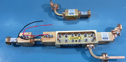
Figure 2 Example of an E-Band signal chain.
A few suppliers do market space-qualified E-Band subsystems because there is some demand for such components. Because of the wavelengths at E-Band, the components typically use WR-12 waveguide requiring precise cavity dimensioning and fabrication. The gap transition tolerances must be extremely small to avoid excessive VSWR and insertion losses. Figure 2 shows a couple of typical E-Band subsystems, integrating filters, amplifiers and waveguide sections.
We predict that InP low noise amplifier (LNA) technology or some exotic heterojunction high bandgap materials with super low noise figure will be required in both the spacecraft and gateways for E-Band systems. Hughes’ estimates a 2 to 3 dB noise figure is needed in the gateway, possibly relaxed to 4 dB in the spacecraft. Based on the component and antenna requirements, the technologies being proposed for the PAs and LNAs at both ends will be tube based, possibly some solid-state PAs. High-power, linear tubes will be considered, and GaN may play a role in the PA, depending on timing. Hughes is currently conducting detailed tradeoffs to determine the best technologies and the manufacturers able to support space-qualified E-Band Tbps systems.
This same assessment process applies to the gateway and spacecraft antennas. Composite materials with very low surface roughness are feasible for the antennas as long as the tolerances are precise.
PROPAGATION LOSSES
The free-space path loss (FSPL) is the expected attenuation of an electromagnetic wave as it travels away from the source. In the far field, it increases proportional to the square of the frequency:
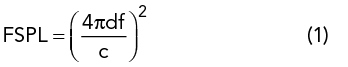
where d is the distance, f the frequency and c the speed of light.
The satellite and ground antenna gain also increases proportional to the square of the frequency:


Figure 3 Rain attenuation vs. rainfall vs. frequency.2
where G is the gain expressed as a ratio, D is the antenna diameter and k is the antenna efficiency factor. Since there are two antennas in the gateway link—at the satellite and on the ground—as frequency increases, the increase in the gain of one antenna will compensate for the FSPL increase. The increase in the other antenna’s gain will at least partially compensate for the increased loss due to rain (see Figure 3). At E-Band, light rain will add 2 dB/km atmospheric attenuation, while links in tropical regions must be designed for approximately 30 dB/km.
Although antenna gain increases with frequency, surface imperfections will degrade the gain, also proportional to the square of the frequency. This change in gain can be estimated by Ruze’s equation:

where ΔG is the change in gain in dB and ϵ is the RMS surface imperfection.
It may seem that the higher antenna gain at higher frequencies can be used to reduce antenna size, but the higher gain is needed to overcome higher atmospheric loss. In dB, the FSPL can be expressed as

Equation 4 is the free-space attenuation calculation for point-to-point microwave transmission in the frequency bands permitted by ITU-R, from ITU-R P.525. Comparing the FSPL values for Ka-, V- and E-Band:
- For a 36,000 km geostationary (GEO) orbit at Ka-Band (27 GHz), the FSPL is 212 dB
- For the same GEO orbit at V-Band (50 GHz), the FSPL is 217 dB
- For the same GEO orbit at upper E-Band (86 GHz), the FSPL is 222 dB.
The E-Band FSPL is 5 dB greater than the value at V-Band and 10 dB above the Ka-Band level. To maintain similar link margins, one option is to increase the power of the PAs at both the ground station and satellite. Unfortunately, high-power E-Band PAs for ground gateways and commercial satellites are virtually nonexistent. With satellite power being a precious resource and ground-based PAs already as large as practical to minimize antenna size, other solutions are needed.
T&M COMPLEXITY
Generating wideband, digitally modulated signals at V-Band and above is challenging and typically requires multiple instruments. The latest signal and spectrum analyzers, like the Rohde & Schwarz FSW67 and FSW85, are the first to operate in V-Band (up to 67 GHz) or in E-Band (up to 86 GHz), respectively, without using external frequency conversion.
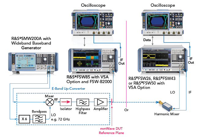
Figure 4 Test setups for E-Band component characterization.
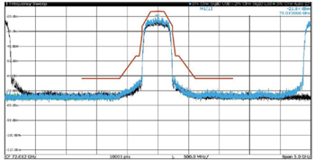
Figure 5 500 MHz bandwidth signal at 72 GHz, showing the image offset by 2.6 GHz.
One possible setup for E-Band signal generation and analysis for wideband satcom channels is shown in Figure 4. For E-Band signal generation, an up-converter using discrete components was employed, comprising a ×6 multiplier because of its commercial availability and other components operating at E-Band. Figure 5 shows a 500 MHz bandwidth E-Band input signal using the FSW signal and spectrum analyzer and the FS-Z90 harmonic mixer. The input and image frequency signals are 2.6 GHz apart. With this spacing, measuring the spectrum mask or analyzing modulation quality of wider bandwidth signals is straightforward. The bandpass filter after the multiplier must be chosen to eliminate the higher harmonics generated by the multiplier from appearing at the mixer local oscillator port, which will cause spurious signals in the up-converter’s output.
ONGOING R&D
E-Band satcom is becoming more suitable due to the growing demand for users to connect to the internet at higher data rates, which requires higher data capacity from commercial VHTS systems. Of the available satcom spectrum, E-Band offers the highest feasible data rates. This article has described some of the challenges to be addressed, such as the frequency plan, availability and performance of RF components and T&M complexities.
To evaluate the feasibility of E-Band for commercial VHTS systems, Hughes is investigating the following:
- Modeling links using commercially available and custom components
- Analyzing the RF conversation signal flow in the gateway and spacecraft
- Researching solid-state and traveling-wave tube PA technologies
- Researching antenna system requirements and design options
- Testing E-Band gateway and spacecraft links with modems to demonstrate link closure
- Characterizing wideband modulated signals suitable for high capacity links.
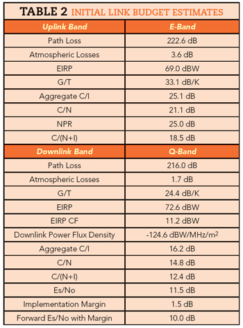
Table 2 shows a preliminary E-Band link budget. This is being refined as Hughes models the gateway and spacecraft forward and return paths and performs studies and benchtop tests with RF components from various suppliers. As noted, these studies are evaluating conversion schemes, various modulation and 1 to 2 GHz instantaneous bandwidth channels. Noise figure, output power, link gains and losses, phase noise, spurious, EVM and other communication system metrics are being measured, with the results used to update the link budgets and system architecture. Hughes plans to provide a future article for Microwave Journal readers, reporting on the results of these studies.
A natural question is, “What is the potential timeline for using E-Band for Tbps communications satellites?” Today, Hughes estimates five to 10 years based on the availability and viability of space-qualified E-Band components, supplier participation and leveraging benefits from terrestrial 5G systems.
References
- Y. Antia, D. Roos and S. Morrar, “The Hughes JUPITER System: Powering a Connected Future,” Microwave Journal, October 2019.
- Recommendation ITU-R P.618-12, “Propagation Data and Prediction Methods Required for the Design of Earth-space Telecommunication Systems,” July 2015.