
MEMS Switch-Based Differential Delay Shifter for a 3.5 GHz Beam Steering Antenna

Figure 1 Four-element array and incoming plane wave.
Antenna arrays consisting of multiple radiating elements are widely used in both defense and commercial applications. The individual elements of the antenna array are usually fed with signals of different phases to form the desired radiation pattern, generally a beam or multiple beams. The beam can be steered by controlling the phase of the signals feeding each element, and the amplitudes of the signals are often optimized to minimize sidelobe radiation.
Cellular base stations widely use phase shifters to adjust the “down tilt” of the antenna, called remote electrical tilt (RET), which is used to optimize coverage and minimize interference. This enhances performance, such as increasing capacity, coverage and signal strength. The move toward sophisticated massive MIMO (mMIMO) solutions is an advanced form of beam steering, with the disadvantage that a separate radio is required for each antenna element. Yet significant performance gains can be made at much lower cost than mMIMO, using fewer transmitters and feeding the antenna elements with adjustable phase shifters. The growing momentum in spectrum rollout for the Citizens Broadband Radio Service (CBRS) for 4G and 5G networks will demand increasingly complex multi-array antennas with advanced beam steering to deliver the required quality of service and high data rates for cellular, enterprise and industrial IoT applications. As these applications are very cost sensitive, an adaptable beam former fed from a single transmitter offers significant value.
This article describes a beam steering antenna for the 3.6 GHz CBRS band using MEMS switches. The design supports high-power operation and uses delay lines configured in a patent-pending differential delay shifter (DDS). Although the common term for antenna beamformers is a “phase shifter,” the required network is actually a “delay shifter” to maintain the desired beam direction over a wide range of frequencies. Incorporating SP4T MEMS switches and delay lines with standard surface-mount packaging yields a highly compact and integrated form factor. This novel approach creates an all-electronic miniaturized delay shifter that can replace the large and bulky mechanical phase shifter components and motors often used for RET in traditional base station antennas. This all-electronic configuration allows for both horizontal and vertical antenna beam steering, with a significant improvement in switching speed and reliability compared to mechanical designs.

Figure 2 Traditional (a) and switched (b) phase shifters.

Figure 3 Two differential delay shifters feeding a four-element array.

Figure 4 Four-step delay shifter differential delay vs. frequency.

Figure 5 Simulated radiation pattern for two beam angles.

Figure 6 Feed network topology.
THEORY OF THE SWITCHED DDS
Consider a simple antenna array receiving a signal (see Figure 1). For a given angle of arrival, θ, the extra distance a signal travels to each element is l1, l2, l3 and l4, respectively. The time for the signal to travel these distances is independent of frequency and is simply a function of the element spacing, the angle of arrival and the propagation velocity, which is usually the speed of light in free space. By adjusting the time delay of each element’s feed for a given angle of arrival, the signals can be combined in phase at the common feed.
Although the time delay elements can be replaced with phase shifters, to ensure a constant beam angle versus frequency, the phase shifters must be adjusted for the specific frequency. This limits the operational bandwidth of the antenna; if the operating frequency is too far away from the design frequency, the direction of the antenna pattern will shift. If the angle, θ, is changed and the beam steered by rotating the incident plane around the center of the antenna, then any change in l1 is equal and opposite to the change in l4. Similarly, the changes in l2 and l3 are equal and opposite. By feeding pairs of elements symmetrically spaced around the center of the array with a differential delay shift network, these conditions are met.
In existing adjustable down tilt antennas for cellular base stations, this functionality is typically achieved using a mechanism controlled by a stepper or servo motor (see Figure 2a). The evolution from this conventional electromechanical phase shifter to a switched topology is shown in Figure 2b. Using discrete, quantized steps for the phase/delay adjustment eliminates the need for large mechanical movement, with more switching steps available to give finer resolution for more accurate beam steering applications. In both topologies, the single input is fed to two antenna elements with the appropriate impedance matching, since the two element impedances appear in parallel to the input. By adjusting the phase/delay, any length added into one path is equally subtracted from the other path, giving true differential phase control.
Figure 3 shows how two of these delay shifters with different transmission line lengths may be used to feed the simple four-element array shown in Figure 1. In this case, delay shift DS1 has 3x the delay variation as DS2, since the end elements are separated by 3x the unit element spacing. Although the schematic shows a direct feed to both delay shifters, an asymmetric power divider can be used to provide amplitude weighting or tapering of the individual elements.
3.6 GHz DDS DESIGN
A four-step DDS for the 3.6 GHz CBRS band was developed using the Menlo Micro MM5130 high-power SP4T switch. Using additional switches, this concept can be extended to eight or 16 delay steps. In this configuration, a key requirement for the switch is a series-only topology with very low parasitic capacitance for the off ports of the switch. This ensures low loss, wideband performance, as the effect of any parasitic capacitance is minimal.
Figure 4 shows the wideband performance of the four-step delay shifter used for the outer pair of elements shown in Figure 3. The maximum differential delay is approximately 0.16 ns, which corresponds to a propagation distance, d, of 50 mm. For an array with an element spacing, s, of 43 mm or λ/2 at 3.6 GHz, the beam steering angle is given by

where N is the number of elements between the two outputs of the delay shifter. In this case, N = 3, so the beam steering angle is 21 degrees. Figure 5 shows the simulated radiation patterns for the four-element array at ±21 degrees. The amplitude weights on the elements was adjusted to give sidelobe levels of -24 dB, a reasonable compromise between the main beamwidth and the sidelobes.
DELAY SHIFTER DESIGN
Practical design considerations were considered when selecting the number of elements for the array, with a 4 x 2 array the minimum number of elements to achieve the desired beam steering (see Figure 6). This array configuration requires three types of delay shifters: one for azimuth to switch the pattern among left, boresight and right and two types for elevation. The azimuth delay shift was configured to have three beam positions, -30, 0 and +30 degrees. This is enough for the relatively wide azimuth beam created by the two elements in each row of the array.

Figure 7 Keysight EMPro 3D model of the delay shifter.

Figure 8 Testing the differential delay shifter prototype.

Figure 9 Feed network with three types of delay shifters.
The first elevation delay shifter controls the delay states between the two inner patch elements, while the second controls the delay state of the two outer patches. Since the distance between the two outer patch elements is 3x the distance between the two middle elements, the corresponding delay shifter was designed with 3x the delay shift. In total, the feed structure encompasses five delay shifters: one for azimuth, two inner pair and two outer pair for elevation. Since the selected switch is a SP4T configuration, the array design uses four delay states in the elevation/vertical plane. Four is not a hard limitation; it can be extended using higher throw switches or several switches in parallel.
The three different types of delay shifters were designed using Keysight ADS and verified and fine-tuned using Keysight EMPro. A multidimensional three-port S-parameter file was exported and used in the top-level simulation. A rendering of the outer pair delay shifter simulation model in Keysight EMPro is shown in Figure 7. Figure 8 shows the outer pair delay shifter being tested. The passive components on the input port provide matching to 50 Ω, so multiple elements can be cascaded, making it relatively straightforward to connect multiple delay shifters in series to form a feed network to control the pattern for both azimuth and elevation.
FEED NETWORK AND RADIATOR DESIGN

Figure 10 4 x 2 element patch array with ground plane.
Reusing the layouts from the three individual delay shifters, the antenna feed board was designed to mate to the backside of the antenna radiator board. The top and bottom element of each vertical column are fed with couplers, which provides unequal power for tapering and enhancing sidelobe suppression. Equal length lines were used to properly phase the inner and outer pairs. To reduce transmission line losses, microstrip lines transitioned to coplanar lines for the delay shifter layouts. Figure 9 shows the feed network with the three types of delay shifters, the combination of microstrip and coplanar waveguide and a USB control in the lower right.
The radiating elements were designed as planar patches backed with a ground plane, which provides a low profile (see Figure 10). The feed position and patch shape were chosen for linear polarization, with dual polarization angle coverage. Antenna efficiency is determined mainly by the losses in the substrate between the elements and the ground plane. To achieve good efficiency, a low loss PTFE with a height of 0.187 in. was selected, with a simulated efficiency of -0.3 dB. Since ground currents from the feed network transmission lines can distort the antenna radiation pattern, the antenna ground plane was separated from the feed board ground plane, which solved several other mechanical issues.

Figure 11 Array 3D gain pattern, azimuth at boresight and elevation +6.5°.
The element spacing in the array is an important design variable. Higher spacing usually results in higher peak lobe gain but increases the undesired grating lobe when the antenna is operating at high steering angles. The clean spurious lobe beam steering range is also determined by the number of rows and columns in the array. Since the design was selected to have only two columns, together with a large azimuth steering range, a traditional λ/2 spacing was selected.
To achieve lower sidelobes in the radiation pattern, -20 dB Taylor amplitude tapering was used in the elevation plane. With only four rows in the array, this tapering applies to the top and bottom rows, with no tapering possible across the two columns, i.e., the azimuth plane. To implement the tapering, rather than power dividers and attenuators, two couplers were used to feed the outer elements, which significantly improves the antenna system efficiency versus traditional methods. A simulated antenna pattern is shown in Figure 11, and the simulated system efficiency in all 12 beam states - three in azimuth and four in elevation - is shown in Figure 12. A simple USB interface controls the delay shifters steering the beam.

Figure 12 Simulated antenna efficiency vs. 12 switching states.
The antenna design was performed using Altair FEKO, a 3D electromagnetic (EM) tool which has method of moments, finite element, finite difference time domain and hybridization solver engines. The high-level design was performed using the finite array tool, which drastically reduced the simulation time and memory. The feed network was designed with Keysight Genesys using the S-parameter files for the delay shifters exported from the EMPro EM simulator. The completed feed network was then exported as a nine-port S-parameter file (one feed port and eight antenna ports) used in the antenna radiation pattern simulation in FEKO.
MEASURED PERFORMANCE
For antenna testing, a plastic 3D-printed radome was designed with transparent windows on the front and back, which shows the interconnection of the delay shifters (see Figure 13). Radiation tests confirm the beam can be controlled in both azimuth and elevation in three and four steps, respectively (see Figure 14). The overall efficiency of the antenna system was greater than 40 percent with greater than 10 dBi gain at a beam position of +6.7 degrees. As the beam was steered to greater angles, the loss in both the delay shifters and antenna elements increased slightly, reducing efficiency.

Figure 13 CBRS antenna in anechoic chamber.
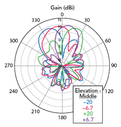
Figure 14 CBRS antenna measured radiation patterns.
SUMMARY
A novel DDS was designed, mimicking the traditional mechanical RET phase shifters yet using the discrete states of a high performance MEMS switch to emulate the positioning of an analog phase shifter. Implemented in a CBRS antenna yielded a highly efficient and lightweight antenna demonstrator, able to change the position of the beam within 10 μs - impossible with a mechanical phase shifter. Table 1 compares the performance of the DDS design to the mechanical and typical solid-state phase shifters. The main performance benefits of the DDS design are power handling, power consumption, IP3 and insertion loss. The broadband capability of the DDS enables it to be extended into the mmWave bands to support future beam steering antenna systems for 5G, aerospace and defense. Other planned design improvements include increasing the integration to realize simpler surface-mount designs and reduce the footprint.

Acknowledgment
This article reflects the contributions of Christopher Mobbs, consultant; Mats Lindstrom, CEO of RF2B; and Marten Seth, a senior systems applications engineer at Menlo Micro.