
Tutorial and Research Trends in Antenna Technology
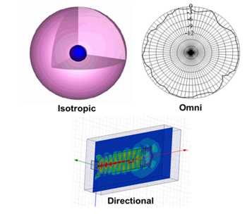
Antennas and antenna arrays serve as the “eyes and ears” for all wireless systems.1-6 According to IEEE Standard (145-1983),7 an antenna may be defined simply as “a means for transmitting and receiving radio waves.” The antenna serves as a transducer between the transmitter and the free space or between the medium and the receiver. In a broad sense, antennas may be classified into three categories, namely isotropic, omnidirectional and directional (see Figure 1). The isotropic antenna is a hypothetical concept of unity gain in all directions.3 It serves as a benchmark by which to measure practical antenna elements. An omnidirectional antenna is the closest realization of an isotropic antenna with almost constant gain in one plane of reference (azimuth or elevation),3 finding widespread use in broadcast applications. Directional antennas have higher directional gain and narrower radiation patterns (beams), desirable for applications like radio detection and ranging (radar) and point-to-point communications.1-6
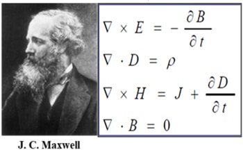
Michael Faraday, in 1830, introduced loop antenna as the part of his experiments studying the coupling of electric and magnetic fields.8 Later Heinrich Hertz8 discovered electromagnetic (EM) waves and designed a dipole antenna. In 1901, Guglielmo Marconi8 sent information across Atlantic Ocean using multiple vertical wires connected to the ground. This was the first use of antenna arrays.3 Maxwell3, 8 wrote the first treatise on EM theory congregating principles postulated by Oersted, Faraday, Gauss and others, popularly known as Maxwell’s equations (see Figure 2). It is shown by Maxwell that any accelerated charge radiates, and hence, an antenna may be defined as an EM device that controls the flow of the time varying currents; thereby, producing EM radiation.
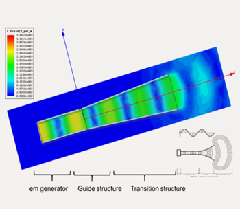
The antenna structure may be considered to have three sections, namely an EM generator, a guiding structure and a transition region (see Figure 3). Figure 3 is the result of a finite element method (FEM) simulation of a horn antenna showing the flow of rf energy in the respective sections. An EM generator inputs the EM wave into the guiding structure (the input of the flared horn), which directs it into the transition region. The transition region is a matching transformer, matching the impedance of guide with 377 ohms, the free space impedance. The EM wave escapes from the transition region into the free space, hence, causing the antenna to radiate.
Although the list of existing antenna types is too vast to summarize here, a few are selected and discussed, based on their commercial and military applications.
Antenna Basics
Antenna Qualifying Parameters (AQPs)
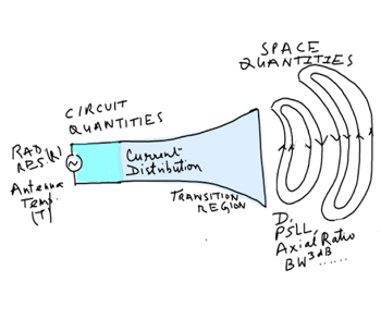
An antenna may be described quantitatively in terms of space and circuit parameters (see Figure 4). AQPs define the radiation and the impedance characteristics of an antenna, respectively, and are listed below:3
1. Antenna Gain, G and directivity (directive gain), D
2. Antenna temperature, T
3. Radiation resistance, R
4. Half power beam width, BW3dB
5. Pointing, look direction or scan angle
6. Sidelobe level (SLL) characteristics, such as peak SLL (PSLL), average SLL (ASLL).
7. Cross-polarization (x-pol) characteristics
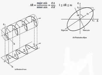
8. Axial ratio (AR)
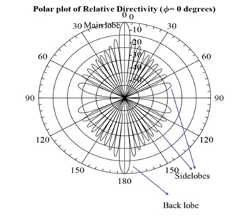
G measures directionality of an antenna pattern with reference to an isotropic antenna (G=1), thus, measurable in dBi (i for isotropic). It is different from D in the sense that it accounts for the various losses in conductors, space (radiation) and guides (dielectric or air),3 not included in directive gain, D. Hence, G is always less than D. BW3dB is the angular distance between the two – 3 dB points from the maximum, or peak, of the radiation pattern’s main beam. Look direction defines the direction in which the antenna pattern’s main beam is pointing while the array is scanning mechanically (using servo motors) or electronically (using digitally applied phase shifts to the elements of an array).4 Figure 5 shows a typical radiation pattern for a directional antenna. Apart from the main lobe (ML), which is desired, there are other unwanted lobes of much smaller magnitude in comparison to the ML, called sidelobes and characterized by SLL.
Antenna Classification
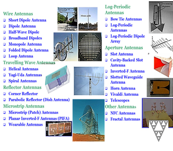
Figure 7 shows a classification of various antenna geometries. It includes wire antennas, traveling wave antennas, reflector antennas, microstrip antennas, log-periodic antennas, aperture antennas and others such as near field communications (NFC) antennas and fractal antennas. An individual antenna element may have a gain from 0 dBi (monopole) to 10-12 dBi (e.g. tapered slot antenna and helical) depending upon the type.
Depending upon specifications such as power handling, G, SLL, size, weight and volume, a class may be chosen for certain applications. Astronomical radio telescope antennas, for example, require very high gain and high-power handling capabilities along with open installations in large areas exposed to different, and often severe, topological and environmental conditions. These requirements are typically fulfilled by reflector antenna arrays.3 For platforms with limited real estate such as high altitude platforms (HAPS)2 and fighter aircraft, microstrip antennas are useful, being light weight, low profile and conformable in nature. Traveling wave antennas and log-periodic antennas are very useful for ultra-wideband and high-power handling applications. Fractal antennas are useful for realization of embedded antenna structures inside mobile handsets. The planar inverted folded antenna (PIFA) is a good structure for body-wearable conformal antennas applications. Antenna arrays are useful for applications such as radar, requiring high gain for detection at longer ranges and directional beams for target tracking.4
Antenna Arrays
Some applications require antennas with high gain, narrow BW3dB and electronic beam steering. These are requirements that cannot be met easily with a single antenna. For these applications, antenna clusters known as antenna arrays must be used.3 For a N-element array, G equals N times the single antenna gain, Go, i.e,

BW3dB is inversely proportional to G, i.e.,

typically for equally fed array elements.3
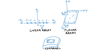
Antenna arrays can be classified into three main categories (see Figure 8):
- Linear antenna array (LAA), consisting of a one-dimensional cluster of antenna elements.
- Planar antenna array (PAA), consisting of a two-dimensional cluster of antenna elements.
- Conformal antenna array (CAA), consisting of a one- or two-dimensional cluster of antenna elements arranged conformally over a surface.
Generalized Expression for Directivity, D
D of an antenna array may be defined as9

where Po is the average radiated power and  is the maximum radiated power in a given direction.
The directivity and gain of antenna are related by

 represents the reflection coefficient of the antenna (circuit parameter) defining mismatch in the transition region of the antenna that matches the characteristic impedance of the guiding structure with that of free space for maximum transfer of energy to space from the antenna structure. Thus, G < D due to conductor, dielectric and mismatch losses.3, 9
The operational bandwidth (OBW) of an antenna may be defined as the range of the frequency points over which the antenna space and circuit parameters, measurable in terms of AQPs, are within desired limits defined by the user. The OBW may be classified in terms of radiation bandwidth and impedance bandwidth.3
Research Trends in AntennaS AND Antenna Arrays
Several current research areas include, but are not limited to:
1. Microstrip reflect arrays
2. Reconfigurable microstrip antennas
3. Body-wearable antennas
4. Multiple input multiple output (MIMO) antennas
5. Ultra-wideband antennas (UWB)
6. Metamaterial antennas
7. Connected array antenna
8. Windscreen antenna
9. Fractal antennas
10. Smart antennas
11. Defected Ground Structure (DGS)/electromagnetic band gap (EBG) Antennas
12. Conformal Antenna Arrays
13. Shared Aperture Antennas
14. Radar antennas
Microstrip Reflect Arrays
The concept was introduced by Berry et al.10 in 1963 using waveguide and was later realized using microstrip technology.11-16 Reflector antennas and phased arrays form the working principle for reflect array antennas (see Figure 9). The variation in size and geometry of planar antenna elements leads to an equivalent phase shift imitating parabolic reflector behavior. The reflector intercepts the impinged wave from a radiator placed at its focal point and scatters back the energy, which collimates due to its designed geometry, and forms a radiated beam. It has associated space loss and spillover loss. A phased array, on the other hand, includes an RF network including phase shifters, attenuators, amplifiers and feed network to receive/transmit energy; thus, there is an associated RF loss. A reflect array antenna overcomes these issues. A reflect array is a phase transformation structure where most of the elements are near resonance; hence, it provides an alternative to a conventional parabolic reflector antenna.
Samaiyar et al.14 discuss an application of reflect arrays for the realization of simultaneous transmit and receive operation at 5.8 GHz in the ISM band. Fukaya et al.15 describe a Tx and an Rx reflect array satellite antenna comprising multiple horns and a single-layer flat reflect array that radiates scanning beams along different directions in azimuth by virtue of polarization and frequency. A reflect array designed using tightly coupled dipole arrays (TCDAs) operates from 3.4 to 10.6 GHz.16 The microstrip reflect array antenna has been demonstrated to be a practical alternative to bulky reflector antennas and costly phased arrays.
Reconfigurable Microstrip Antennas
Reconfigurability in antennas is desired to eliminate the need to employ multiple antennas for diverse characteristics such as polarization, frequency and radiation patterns.17-21 Reconfigurability is achieved by modifying substrate properties or physical dimensions using switches or tunable materials. Substrate material properties directly affect the resonant frequency (inversely proportional to relative permittivity and permeability) and the operational bandwidth (directly proportional to thickness of the substrate) of microstrip antennas. Ferroelectric or ferrite material can vary permeability by application of a DC bias field, thus, controlling an antenna’s resonant frequency by varying its electrical dimensions.18
Conductor dimensions in microstrip antennas can control radiative properties (see Figure 10).19 Figure 10a shows a microstrip rectangular patch (MRP) with an outer ring connected to an inner one through diodes. By switching the diodes ‘on’ and ‘off,’ the MRP size is altered, varying its resonant frequency. Figure 10b shows reconfigurability in polarization by virtue of shorting posts placed diagonally inside the patch. Figure 10c shows a common aperture supporting two antennas, a receive antenna (total aperture) and a transmit antenna (inner circle) in a shared manner, demonstrating reconfigurability of two radiating modes.

Body-Wearable Antennas
Body-wearable antennas have immense potential in applications for body area networks (BANs), wireless area networks (WANs), health monitoring and diagnosis and body-to-body communication.22-30 Figure 11 illustrates one use case of a person communicating to a body-mounted sensor with that sensor communicating to a remote health provider for monitoring and to a satellite for remote data collection. The antenna is in close proximity to the body and is very challenging to design in terms of the impedance matching, specific absorption rate (SAR), size, cost, weight, volume and conformability. Mandal et al.29 describe a low profile, circularly polarized, “button antenna” for Wi-Fi and WLAN applications with a frequency selective structure (FSS) to suppress back radiation. Njogu and Sanz-Izquierdo30 demonstrate a fingernail-shaped antenna for on body communications.

Fig. 11 Body-wearable antenna use case.
MIMO Antennas
MIMO31-33 is a radio antenna technology using multiple antennas at the transmitter (Tx) and receiver (Rx) to provide multiple signal paths for carrying data (see Figure 12). MIMO can enable beamforming, transmit diversity and receive diversity. Diversity techniques protect against fading and improve coverage in an urban scenario. MIMO spatial multiplexing uses the same frequency to transmit different signals. Massive MIMO (M-MIMO)32-33 uses large numbers of phased antenna arrays instead of active terminals and time-division multiplexing. Energy is focused into small spatial regions for high radiated energy efficiency and throughput. M-MIMO is important for 5G applications.

Ultra-Wideband (UWB) Antennas
UWB antennas34-40 are used in low power and short-range applications due to the limitation of pulse forming networks. An UWB transmitter in the U. S. is defined as an intentional radiator that, at any point in time, has a bandwidth equal to or greater than 500 MHz or a fractional bandwidth (FBW) greater than 0.2. Antenna design is challenging. UWB antennas should have flat group delay over their bandwidth. The FBW of UWB is defined as

The U.S. Federal Communications Commission (FCC) has authorized unlicensed usage of UWB systems below the 960 MHz and in the 3.1 to 10.6 GHz band with very low effective isotropic radiated power (EIRP). The FCC power spectral density emission limit for UWB transmitters is −41.3 dBm/MHz. The challenges in design of UWB antennas are: achieving consistent gain, HPBW, polarization and phase over the UWB; realizing a small antenna size (low profile) to fit into commercial systems; and controlling cost.
Many antenna designs belonging to the family of traveling wave antennas like log-periodic dipole antennas (LPDAs), Vivaldi antennas and spiral antennas have been developed to achieve UWB; however, they have large profiles and are bulky, making them impractical for wireless communication systems. Over the last decade there has been much research on planar monopole antennas for UWB.36-37, 39 The ground plane of these antennas is kept small to attain a low profile. Hence, design activity should consider the antenna ground plane in system design and optimization.
Nunn et al.39 describe an UWB circular monopole antenna array for surface-based ice sounding in the UHF Band. It comprises 16 planar subarrays forming a 16 x 17 m Mills cross array that maximizes sensitivity and spatial selectivity in both cross- and along-track directions. An insulation foam separates the ground plane from monopole such that maximum radiation is directed broadside. Nie et al.40 report on a two-port coplanar waveguide (CPW) fed UWB antenna with high isolation between ports and a common ground. Designed for full hemispherical coverage, its isolation is greater than 31.4 dB with a diversity gain of 10 dB from 2.98 to 10 GHz. A 2.5 dB gain with efficiency better than 80 percent is also demonstrated.
Metamaterial Antennas
Metamaterials are electromagnetic structures with unusual properties that are not seen in nature:41, 42
- Double negative (DNG) materials

- Negative Refractive Index

- Left-Handed
- Single-negative (SNG) materials
 (E – , H – fields and wave vector do not follow the right-hand rule.)
 - Backward wave (energy flow is anti-parallel to wave vector)
DNG materials cause the phase velocity and power flow to be anti-parallel; thus, cut-off waveguide realization is not hypothetically feasible. The challenge is the fundamental limitation with respect to an antenna’s quality factor and its electrical size. Resonances in these materials make it possible to design smaller antennas (see Figure 13).42 Although thin and measuring only a few millimeters these multiband antennas double the range and enhance reliability and battery life of mobile phones, Wi-Fi routers and wireless modems.

Connected Array Antennas
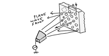
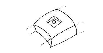
Wheeler43 introduced the concept of a continuous current sheet (CCS) that radiates a transverse electromagnetic (TEM) wave (see Figure 14a). The radiation resistance, R, of the current sheet with a ground plane separated by λ/4 is 120π Ω at
broadside and leads to a hypothetically infinite bandwidth. The CCS absorbs an incident plane wave without any reflection. For an E-plane scan with an incident angle  the boundary resistance is proportional to cos due to the cosine projection of the E-field on the aperture; and, for H-plane scan, the boundary resistance is proportional to cos - 1. In reality, however, an infinite and uniform current sheet is not feasible. Munk44 was the first to demonstrate it practically utilizing interconnected antenna elements with a 5:1 bandwidth dipole array called a ‘current sheet array’ (CSA) (see Figure 14b). TCDAs are being researched to yield more efficient forms of CSAs.3, 38, 45

Windscreen Antennas
The automobile industry is introducing multiple on-board sensors for safety and entertainment.46 Figure 15 shows a car supporting various antennas connected to its body (f1, f2, f3, f4, etc.). Cars require antennas for music (f3), file sharing (f2), navigation (f1) and anti-collision radar (f4) systems. They require GPS antennas for navigation and antennas to support various sensors such as rain and sleep sensors. The challenges are to achieve a small form factor while mitigate the effects of mutual interference between the multiple sensors, as well as the effect of the vehicle’s body on performance. The design process is not simple and requires hybridization of various low frequency design techniques such as the method of moments (MoM) and FEM with high frequency design techniques such as the uniform theory of diffraction (UTD) and shooting bouncing ray (SBR).47, 48

Fractal Antennas
A fractal is a fragmented geometrical shape that looks the same, independent of size scaling. A fractal shaped metal element can be used as an antenna over a very large band of frequencies demonstrating self-similarity and scaling independence. Mandelbrot coined the term in 1983,49 but the origin dates back to von Koch in 1904.50 He showed that it is possible to devise a curve without a tangent, anywhere. The most popular fractal shapes used for antennas are the fractal carpet, Sierpinski’s gasket, Cantor’s comb, von Koch’s snowflake, the Mandelbrot set and the Lorenz attractor. One significant property of all these fractals is their irregular nature. Figure 16 shows some typical fractal antennas.
 Fig. 16 Typical examples of fractal antennas.
A few recent publications,52, 53 demonstrate new types of fractal antennas such as the flower fractal and fern fractal leaf inspired Vivaldi antennas. Mondal et al.52 describe a flower fractal based circularly polarized folded microstrip patch antenna with 49 percent miniaturization, 110 degree 3 dB beamwidth and 120 degree AR beamwidth. A nature inspired fern fractal leaf structure demonstrates an impedance bandwidth of 19.7 GHz and a gain of 10 dBi.53
Smart Antennas
The smart antenna is a misnomer. It is actually a smart system combined with an antenna structure. It is used for applications such as direction of arrival (DoA) estimation, adaptive beamforming and adaptive null formation.54, 55 Figure 17 is an analogy comparing a smart antenna system with a blinded man and two speakers. The blinded man can “tune” his ears to hear one speaker while ignoring the other one. Similarly, a smart antenna system can suppress interference from one direction and enhance reception of a signal from the desired source. MIMO is one example of a smart antenna system; it is not a separate type of antenna but an intelligent system of existing antenna types.

DGS Antennas
In practice, an antenna must be mounted on some structure, which may be an aircraft, ship or a stationary structure like a cell phone tower. Conventionally, to facilitate analysis, antenna design assumes an infinite ground plane or a finite ground plane with good planarity. Mounting structures affect antenna performance because they do not satisfy the precise conditions assumed in design. Figure 18 is a sketch showing the effect of the platform on an antenna pattern. The black and the blue curves show a hypothetical antenna pattern without and with the effect of the airborne platform, respectively.

DGSs or EBG structures derived from photonic band gap (PBG) structures offer a convenient solution. DGSs are artificial periodic structures exhibiting characteristics similar to band stop filters. They prevent certain bands of frequencies to pass through. They can be used to realize antenna ground planes locally beneath antennas on mounting platforms to minimize platform interaction.56-58 Obelleiro et al.56 present a detailed study of array antennas mounted on aircraft, ships and other vehicular platforms. They consider the effect of mutual coupling between elements and the platform on antenna performance using MoM analysis, with a degradation in sidelobe levels of up to 15 dB. Kumar et al.57 improve polarization purity by incorporating a DGS integrated with a microstrip antenna. A 12 dB improvement in isolation between co- and cross-polarization patterns is demonstrated. Bell et al.58 achieve profile reduction by using DGS structures. DGSs are important in controlling mutual coupling, enhancing polarization purity, enabling miniaturization and mitigating the effects of non-ideal ground planes in antennas designed for practical applications.
Conformal Antenna Arrays
In airborne applications (i.e. aircraft, missiles) antennas may increase the vehicle’s radar cross section (RCS) and interfere with the aerodynamics. Hence, it is desirable for the antenna structure to be conformal (see Figure 19). Further, conformal antennas are also desirable for the realization of body-wearable antennas.
SHAAS address defense and commercial requirements to combine different antennas that satisfy multiple functions like radar, communications, identification friend or foe (IFF) and GPS into one.4, 55, 56 In some applications like marine cruisers, legacy platforms may have more than 100 separate antennas on board.62 SHAAS solves this problem with a common aperture sharing multiple features (see Figure 20).
The multiple functionalities can be accessed either simultaneously or in a time-sharing mode. The challenges for antenna design are to reduce in-band and out-of-band coupling between operational bands, minimize interaction with the mounting platform, miniaturize the electronics and arrange inter-element grids to avoid grating lobes while mitigating scanning losses.4, 9, 63 Zhang et al.64 describe a dual-band shared aperture antenna utilizing the concept of structure re-use. SHAAS provide a solution for antenna systems to be greener (more efficient), more compact and lower cost.

Radar Antennas
Figure 21 shows the evolution of radar antenna since Hertz conceptualized the first spark plug experiment using a loop antenna. Later, Yagi and Uda (1920) introduced Yagi – Uda antennas, followed by the horn antenna in the 1930s, antenna arrays in the 1940s, parabolic reflectors in the late 1940s and early 1950s, microstrip patch antennas in the 1970s and PIFAs in the 1980s.
Later, mechanically scanned arrays (MSAs) were developed with fixed beam antennas mounted on servo rotor mechanisms. The inertia of a servo system limits the rotation rate, or scan rate, however. To overcome this, passive electronically scanned antenna arrays (PESAs) were developed that rotate, or scan, the beam electronically with phase shifters behind each antenna.
In a PESA, the amplitude distribution across the antenna aperture is fixed due to a fixed power division network at the back-end distributing rf power received from single high-power transmitter (HPT).4 Failure of the HPT represents a single-point-of-failure for the system. Active electronically scanned antenna arrays (AESAs) overcome this problem.
The AESA comprises individual transmitters and receivers, in a single housing, behind each element called a transmit-receive module (TRM).4, 6 A key feature of the AESA is graceful degradation, i.e., the radar operates with limited functionality even in the case of failure of few TRMs (typically less than 10 to 15 percent). The overall design requirements of an AESA may be summarized by the following parameters:
Functional Requirements
- Spatial Scan Volume
- Instantaneous/Operational bandwidth
- Beamwidth
- Peak and average sidelobe level
- Antenna gain
- Polarization
- Peak power and average power output
- Beam switching capability
- Prime power requirement
Physical Requirements
- Size, weight, transportation and mobility
- Production, maintenance and reliability
Environmental Requirements
- Shock and vibration capability
- Operational temperature range
- Humidity, salt, fog and fungus

References
- J. Hoydis, S. Ten Brink and M. Debbah, “Massive MIMO: How Many Antennas Do We Need?” 49th Annual Allerton Conference on Communication, Control and Computing, Monticello, September 2011.
- R. Sturdivent, C. Quan and E. Chang, System Engineering of Phased Arrays, Artech House, U.S.A., 2019.
- C. A. Balanis, Modern Antenna Handbook, 3rd ed., New York: John Wiley & Sons Inc., 2007.
- N. Fourikis, Phased Array-Based Systems and Applications, John Wiley & Sons Inc, New York, U.S.A., 1997.
- R. Weber and R. Weber, Internet of Things, Vol. 12, U.S.A., Springer, 2010.
- A. Kedar, A. S. Bisht, K. Sreenivasulu, D. Srinivas Rao and N. K. Vishwakarma, “GaN based Wide Band C-band Active Phased Array Antenna Design with Wide Scan Volume,” IEEE International Radar Conference, April 2020.
- IEEE Standard Definitions of Terms for Antennas, IEEE std 145-1983, 1983, pp. 1-31.
- T. K. Sarkar and S. Palma, “A History of the Evolution of RADAR,” Proceedings of the European Microwave Conference, December 2014, pp. 734-737.
- A. Kedar and L. P. Ligthart, “Wide Scanning Characteristics of Sparse Phased Array Antennas Using an Analytical Expression for Directivity,” IEEE Transactions on Antennas and Propagation., Vol. 67, No. 2, February 2019, pp. 905-914.
- D. Berry, R. Malech and W. Kennedy, “The Reflectarray Antenna,” IEEE Transactions on Antennas and Propagation, Vol. 6, No. 11, November 1963, pp. 645-651.
- R. E. Munson and J. Haddad, 1987, Microstrip Reflectarray Antenna for Satellite Communication and RCS Enhancement, US patent 4,684,952.
- J. Huang and A. Feria, “Inflatable Microstrip Reflectarray Antennas at X and Ka-Band Frequencies,” Antennas and Propagation Society International Symposium, Vol. 3, July 1999, pp. 1670-1673.
- X. Y. Lei and Y. J. Cheng, “High-Efficiency and High-Polarization Separation Reflectarray Element for OAM-Folded Antenna Application,” IEEE Antennas and Wireless Propagation Letters, Vol. 16, December 2016, pp. 1357-1360.
- A. Samaiyar, A. H. Abdelrahman and D. S. Filipovic, “Simultaneous Transmit and Receive Reflectarray Antennas on Low Cost UAV Platforms,” IEEE International Symposium on Antennas and Propagation & USNC/URSI National Radio Science Meeting, July 2017.
- M. Fukaya, R. Obata, S. Makino, H. Nakajima and M. Takikawa, “A New Satellite Antenna Concept Using Reflectarray Antennas,” International Symposium on Antennas and Propagation, October 2019.
- W. Li, S. Gao, L. Zhang, Q. Luo and Y. Cai, “An Ultra-Wide-Band Tightly Coupled Dipole Reflectarray Antenna,” IEEE Transactions on Antennas and Propagation, Vol. 66, No. 2, February 2018, pp. 533-540.
- J. Constantine, Y. Tawk, S. E. Barbin and C. G. Christodoulou, “Reconfigurable Antennas: Design and Applications,” Proceedings of the IEEE, Vol. 103, No. 3, March 2015, pp. 424-437.
- T. Roach, G. Huff and J. Bernhard, “A Comparative Study of Diversity Gain and Spatial Coverage: Fixed Versus Reconfigurable Antennas for Portable Devices,” Microwave and Optical Technology Letters, Vol. 49, No. 3, January 2007, pp. 535-539.
- D. Schaubert, F. Farrar, A. Sindoris and S. Hayes, “Microstrip Antennas with Frequency Agility and Polarization Diversity,” IEEE Transactions on Antennas and Propagation, Vol. 29, No. 1, January 1981, pp. 118-123.
- Z. Su, M. Vaseem, W. Li, S. Yang and A. Shamim, “Additively Manufactured Frequency/Radiation Pattern Reconfigurable Antenna Based on Monolithically Printed VO2 Switch,” European Conference on Antennas and Propagation, March-April 2019.
- L. Leszkowska, D. Duraj, M. Rzymowski, K. Nyka and L. Kulas, “Electronically REconfigurable Superstrate (ERES) Antenna,” European Conference on Antennas and Propagation, March-April 2019.
- S. M. Abbas, H. Zahra, R. Hashmi, K. P. Esselle and J. L. Volakis, “Compact On-Body Antennas for Wearable Communication Systems,” International Workshop on Antenna Technology, March 2019.
- C. Mendes and C. Peixeiro, “A Dual-Mode Single-Band Wearable Microstrip Antenna for Body Area Networks,” IEEE Antennas and Wireless Propagation Letters, Vol. 16, October 2017, pp. 3055-3058.
- G. A. Casula, A. Michel, P. Nepa, G. Montisci and G. Mazzarella, “Robustness of Wearable UHF-Band PIFAs to Human-Body Proximity,” IEEE Transactions on Antennas and Propagation, Vol. 64, No. 5, May 2016, pp. 2050-2055.
- S. M. Abbas, K. P. Esselle, L. Matekovits, M. Rizwan and L. Ukkonen, “On-Body Antennas: Design Considerations and Challenges,” URSI International Symposium on Electromagnetic Theory, August 2016.
- A. M. Zubair, M. Ali, M. U. Khan and M. Q. Mehmood, “A Compact, Low-Profile Fractal Antenna for Wearable On-Body WBAN Applications,” IEEE Antennas and Wireless Propagation Letters, Vol. 18, No. 5, May 2019, pp. 981-985.
- B. Hu, G. -P. Gao, L. -L. He, X. -D. Cong and J. -N. Zhao, “Bending and On-Arm Effects on a Wearable Antenna for 2.45 GHz Body Area Network,” IEEE Antennas and Wireless Propagation Letters, vol. 15, June 2015, pp. 378-381.
- S. M. Saeed, C. A. Balanis, C. R. Birtcher, A. C. Durgun and H. N. Shaman, “Wearable Flexible Reconfigurable Antenna Integrated with Artificial Magnetic Conductor,” IEEE Antennas and Wireless Propagation Letters, Vol. 16, June 2017, pp. 2396-2399.
- B. Mandal, A. Chatterjee, P. Rangaiah, M. D. Perez and R. Augustine, “A Low Profile Button Antenna with Back Radiation Reduced By FSS,” European Conference on Antennas and Propagation, March 2020.
- P. Njogu and B. Sanz-Izquierdo, “Removable Finger Nail Antenna,” European Conference on Antennas and Propagation, March 2020.
- C. Deng, D. Liu and X. Lv, “Tightly Arranged Four-Element MIMO Antennas for 5G Mobile Terminals,” IEEE Transactions on Antennas and Propagation, Vol. 67, No. 10, October 2019, pp. 6353-6361.
- G. Larsson, O. Edfors, F. Tufvesson and T. L. Marzetta, “Massive MIMO for Next Generation Wireless Systems,” IEEE Communications Magazine, Vol. 52, No. 2, February 2014, pp. 186-195.
- A. Hassanien and S. A. Vorobyov, “Phased-MIMO Radar: A Tradeoff Between Phased-Array and MIMO Radars,” IEEE Transactions on Signal Processing, Vol. 58, No. 6, June 2010, pp. 3137-3151.
- “First Order and Report, Revision of Part 15 of the Commission’s Rules Regarding UWB Transmission Systems,” Federal Communications Commission, FCC 02–48, April 22, 2002.
- Z. N. Chen, “A New Bi-Arm Roll Antenna for UWB Applications,” IEEE Transactions on Antennas and Propagation, Vol. 53, No. 2, February 2005, pp. 672-677.
- M. J. Ammann, “Square Planar Monopole Antenna,” International Conference on Antennas and Propagation, March-April 1999, pp. 37-40.
- N. P. Agrawall, G. Kumar and K. P. Ray, “Wide-Band Planar Monopole Antenna,” IEEE Transactions on Antennas and Propagation, Vol. 46, No. 2, February 1998, pp. 294-295.
- F. B. Gross, Frontiers in Antennas: Next Generation Design & Engineering, McGraw-Hill, 2011.
- J. A. Nunn, L. Li , S. Yan, C. O’Neill, C. D. Simpson, P. Gogineni and D. D. Jensen, “A Lightweight Planar Ultrawideband UHF Monopole Mills Cross Array for Ice Sounding,” IEEE Transactions on Antennas and Propagation, Vol. 19, No. 7, July 2020, pp. 1197-1200.
- L. Y. Nie, X. Q. Lin, S. Xiang, B. Wang, L. Xiao and J. Y. Ye, “High Isolation Two-Port UWB Antenna Based on Shared Structure,” IEEE Transactions on Antennas and Propagation, June 2020.
- V. G. Veselago, “The Electrodynamics of Substances with Simultaneously Negative Values of e and m,” Soviet Physics Uspekhi, Vol. 10, January 1968, pp. 509–514.
- “Rayspan Metamaterial Antennas Reduce Handset Radiation Exposure, Accelerate Testing and Reduce Time to Market,” Rayspan Corporation, January 2010. Web. https://www.prnewswire.com/news-releases/rayspan-metamaterial-antennas-reduce-handset-radiation-exposure-accelerate-testing--reduce-time-to-market-80686252.html.
- H. A. Wheeler, “Simple Relations Derived from a Phased-Array Antenna Made of an Infinite Current Sheet,” IEEE Transactions on Antennas and Propagation, Vol. 13, No. 4, July 1965, pp.506-514.
- B. A. Munk, Finite antenna arrays and FSS, Wiley-IEEE Press, 2003.
- M. H. Novak, F. A. Miranda and J. L. Volakis, “Ultra-Wideband Phased Array for Small Satellite Communications,” IET Microwaves, Antennas and Propagation, Vol. 11, No. 9, July 2017, pp. 1234-1240.
- I. Berger, “As Cars Become More Connected, Hiding the Antennas Gets Tougher,” The New York Times, March 2005. Web. https://www.nytimes.com/2005/03/14/automobiles/as-cars-become-more-connected-hiding-the-antennas-gets-tougher.html.
- “Altair Feko™ Applications,” Altair. Web. https://altairhyperworks.com/product/FEKO/Applications-Antenna-Design-Windscreen-Antennas.
- E. Whalen, A. Elfrgani, C. Reddy and R. Rajan, “Antenna Placement Optimization for Vehicle-to-Vehicle Communications,” IEEE International Symposium on Antennas and Propagation, July 2018.
- B.B. Madelbrot, The Fractal Geometry of Nature, Freeman, N. Y., 1983.
- H.O. Peitgen, H. Jurgens and D. Saupe, Chaos and Fractals: New Frontiers of Science, Springer-Verlag, N. Y., 1992.
- D. H. Werner and S. Ganguly, “An Overview of Fractal Antenna Engineering Research,” IEEE Antennas and Propagation Magazine, Vol 45, No.1, February 2003, pp. 38-57.
- T. Mondal, S. Suman and S. Singh, “Novel Design of Fern Fractal Based Triangular Patch Antenna,” National Conference on Emerging Trends on Sustainable Technology and Engineering Applications, February 2020.
- T. Mondal, T. Chandra, P. Kuila and S. Maity, “A Flower-Fractal Based Circularly Polarized Wide Beam-Width Folded Antenna,” National Conference on Emerging Trends on Sustainable Technology and Engineering Applications, February 2020.
- “Smart Antennas, Circuits Today, Tutorial. Web. https://www.circuitstoday.com/smart-antennas.
- “Smart Antenna Basics,” Wireless World, Tutorial. Web. https://www.rfwireless-world.com/Terminology/Smart-Antenna.html.
- F. Obelleiro, L. Landesa, J. M. Taboada and J. L. Rodriguez, “Synthesis of Onboard Array Antennas Including Interaction with the Mounting Platform and Mutual Coupling Effects,” IEEE Antennas and Propagation Magazine, Vol. 43, No. 2, April 2001, pp. 76-82.
- C. Kumar, M. I. Pasha and D. Guha, “Defected Ground Structure Integrated Microstrip Array Antenna for Improved Radiation Properties,” IEEE Antennas and Wireless Propagation Letters, Vol. 16, May 2016, pp. 310-312.
- J. M. Bell, M. F. Iskander and J. J. Lee, “Ultrawideband Hybrid EBG/Ferrite Ground Plane for Low-Profile Array Antennas,” IEEE Transactions on Antennas and Propagation, Vol. 55, No. 1, January 2007, pp. 4-12.
- K. A. Yinusa, “A Dual-Band Conformal Antenna for GNSS Applications in Small Cylindrical Structures,” IEEE Antennas and Wireless Propagation Letters, Vol. 17, No. 6, June 2018, pp. 1056-1059.
- X. Gao, Z. Shen and C. Hua, “Conformal VHF Log-Periodic Balloon Antenna,” IEEE Transactions on Antennas and Propagation, Vol. 63, No. 6, June 2015, pp. 2756-2761.
- L. Joseffson, Conformal Array Antenna Theory and Design, Wiley, 2006.
- “New Multi-beam Satellite Antenna to Fortify US Navy Ships' Attack Clout,” Sputnik International, May 2020. Web. https://sputniknews.com/military/202005191079347424-new-multi-beam-satellite-antenna-to-fortify-us-navy-ships-attack-clout.
- C. Coman, I. Lager and L. Ligthart, “The Design of Shared Aperture Antennas Consisting of Differently Sized Elements,” IEEE Transactions on Antennas and Propagation, Vol. 54, No. 2, February 2006, pp. 376-383.
- J. F. Zhang, Y. J. Cheng, Y. R. Ding and C. X. Bai, “A Dual-Band Shared-Aperture Antenna with Large Frequency Ratio, High Aperture Reuse Efficiency, and High Channel Isolation,” IEEE Transactions on Antennas and Propagation, Vol. 67, No. 2, February 2019, pp. 853-860.