
Horus: A Testbed for Fully Digital Phased Array Radars
Leveraging years of experience, the Advanced Radar Research Center (ARRC) at the University of Oklahoma (OU) is building the first-ever, mobile polarimetric, all-digital phased array radar (PAR),1 as depicted in Figure 1. As technology has significantly evolved over the last 10 to 15 years, especially in the areas of analog-to-digital converters (ADC), digital-to-analog converters (DAC), high-power amplifiers and field-programmable gate arrays (FPGA), the possibility of moving significant portions of a radar system closer to the aperture of a phased array antenna has become a reality. Figure 2 depicts the overarching architecture of the all-digital PAR system, wherein an independent digital receiver and digital transmitter exist for each horizontal (H) and vertical (V) channel for each of our dual-pol elements.

Figure 1 Genesis of the ARRC’s mobile polarimetric all-digital phased array radar development.
RADAR EVOLUTION

Figure 2 An independent digital receiver and digital transmitter exist for each element.
Over the last 15 years, the ARRC has been engaged in the national Multifunction Phased Array Radar (MPAR) initiative, and subsequently the Spectrum Efficient National Surveillance Radar (SENSR) Program, as initially coordinated by the Federal Aviation Administration (FAA), Department of Defense (DoD), Department of Homeland Security (DHS) and National Oceanic and Atmospheric Administration (NOAA). Consequently, the ARRC is developing a scalable all-digital polarimetric S-Band phased array that addresses the requirements for weather and long-range aircraft scanning. The array will also support other important modes of operation including MIMO and general communications.
Agile beam steering and multifunction capabilities now make phased arrays the best candidates for multi-mission radar systems, offering efficient and cost-effective solutions. Advancements in GaAs, SiGe, CMOS and GaN technology provide reliable, highly integrated and affordable RF components that have enabled phased array antennas to become a core technology for modern remote sensing and communication. High levels of integration and more efficient components have allowed for phased array antenna architectures with multiple transceivers that can be used to increase functionality and performance at reduced cost, size and weight compared to their predecessors that exclusively used analog beamformers: for instance, 5G will certainly leverage phased array technology. Arrays with analog beamforming are inherently constrained to the beamforming scheme imposed by the exact configuration of front-end beamforming electronics.
Presently, digital beamforming (DBF) at the sub-array level is a common approach to increase the flexibility of phased array radars, as demonstrated by the 76-panel Advanced Technology Demonstrator (ATD) operated by NOAA’s National Severe Storms Laboratory (NSSL) and the University of Massachusetts’ (UMass) Raytheon Low-Power Radar (i.e., Skyler). Yet, the move towards element-level DBF architectures offers unprecedented capabilities. Examples of such systems include; Australia’s CEA-FAR naval radar, the U.S. Navy’s FlexDAR radar,2 Israeli Elta’s MF-STAR, AFRL’s BEEMER (Baseband-digital at Every Element MIMO Experimental Radar) and Space Fence, to name a few. Moreover, digital at every element makes exquisite control of polarimetry a possibility, with single H, single V, simultaneous H&V for slant 45, LHC, RHC or arbitrary polarization states.
Digital array technology is a nascent research endeavor; a thrust of Combat Capabilities Development Command Army Research Laboratory’s (CCDC ARL) research is the development of robust techniques for array calibration. Operation in crowded and contested environments depends critically on protecting radar operations and maintaining calibration in dynamic environments. Factory calibration is insufficient for digital arrays, and methods for robust in-situ calibration are needed that are also computationally efficient. In conjunction with partners including OU and CCDC ARL is developing mutual coupling-based calibration techniques to address this problem. CCDC ARL is conducting proof-of-concept experiments to quantify performance of initial algorithms using an element-level digital array laboratory test asset. Moving forward, CCDC ARL will extend these techniques for wider bandwidth performance and focus on scalability to large-format arrays, as well as suitability for operational environments outside of the laboratory test bench.
FULLY DIGITAL ARCHITECTURE
Even though implementation of dual-polarization on PAR has proven challenging, significant progress has been made recently, as reported by a community workshop of radar technologies sponsored by the National Science Foundation (NSF),5 such as MIT Lincoln Lab’s S-Band panels at the ATD,6 BCI/LMCO’s S-Band prototype, NCAR’s C-Band airborne phased array radar system, UMass’ X-Band radar, and OU’s S-Band cylindrical polarimetric phased array radar (CPPAR) demonstrator.7 In order to improve the temporal resolution on spotlight operation, the single-polarized X-Band Atmospheric Imaging Radar (AIR) was developed by the ARRC several years ago, as shown in Figure 1. The AIR operates in a “floodlight” mode, utilizing a 20-degree vertical fan beam on transmit and 36 receiving arrays capable of fine scale digital beamforming. In other words, a range height indicator (RHI) of radar measurements can be formed simultaneously, similar to taking a picture with an electromagnetic camera. This configuration, combined with 20 degrees/sec mechanical scanning in azimuth, allows the current AIR to collect 180 by 20 degree volumes in approximately nine seconds; hence, the world’s highest resolution observations of tornado genesis.8 A similar system with floodlight operation is the X-Band PAR located at Osaka University.
These advanced imaging surveillance modes of operation require digitization of multiple subarray channels. Increased levels of digitization also enable adaptive digital beamforming (ADBF), space-time adaptive processing (STAP) and even MIMO modes of operation. An ideal phased array architecture would feature digitization and control of both the transmitted and received signals at each antenna element, along with the ability to cover wide bandwidths. Because the element-level processing and subsequent beamforming are digital, it can be reconfigured and optimized for different applications. Digitization at the element level opens the door to new processing and beamforming schemes and delivers maximum flexibility with unprecedented dynamic range in large systems. For instance, given M elements and uncorrelated noise at each element, the signal-to-noise ratio of the system is increased by 10log(M). However, this comes with inherent technological risks and practical challenges associated with the amount of data to process and the use of less sophisticated transceivers.
Figure 3 shows three example modes of our all-digital PAR system. The left panel of Figure 3 depicts several typical high sensitivity beams and several low priority beams, which are needed for continuously dwelling in an area to glean important information. The middle panel of Figure 3 depicts a space time multiplexing paradigm whereby sets of independent samples can be collected from a surveillance area; this allows data to be collected with fewer samples. Since adaptive spatial filtering can be achieved via a phased array,4 this greatly demonstrates the use of a phased array over a typical parabolic dish antenna. Finally, the right panel of Figure 3 depicts how our mobile demonstrator will leverage the team’s imaging expertise so that rapid volume scanning may be achieved.8

Figure 3 Three example radar modes that demonstrate the efficacy of an all-digital array.
For any future multi-mission radar, multiple interleaved functions are practically the only way to satisfy the bevy of mission requirements in a given timeline, so advanced beamforming flexibility through digitization is critical. Furthermore, additional missions over the lifetime of a digital PAR could be implemented with software upgrades, rather than costly hardware retrofits, resulting in significant operation and maintenance cost savings. The next section provides an overview of the development of an S-Band, dual-polarization PAR that is being designed and built at the ARRC that will achieve these goals. This system, which we call Horus, has a digital transceiver per polarization, per element and will be a valuable research tool in evaluating the benefits and challenges to such an approach.
DESIGN CONCEPTS OF THE "HORUS" RADAR
A mobile, S-Band, dual-polarized phased array system is currently under development by the ARRC. It has a fully digital architecture, and this system will consist of 1024 dual-polarized elements divided into 25 8x8 panels (16 are populated with electronics) as shown in Figure 4. Each panel houses eight “OctoBlades” wherein virtually all radar electronics reside. Each OctoBlade, which drives an eight-element column of the panel’s high performance antenna array with nearly ideal polarization along the principal planes through careful design, consists of a metal cooling plate (heat transport duct) with PCBs on each side to house a total of 16 GaN-based frontends (>10 W per element, per polarization), eight dual-channel digital transceivers from analog devices, four front-end FPGAs for processing and two FPGAs for control. Antenna sub-systems and their associated electronics can be organized in one of three primary architectures: conformal tile assembly, panel assembly (with slide-out OctoBlades) or separate structures that are separated by cables (see Figure 4). This design with slide-out OctoBlades provides the least maintenance costs since these electronic assemblies are easily hot-swappable. This convenient feature is ideal for ground-based systems that require service lives of several decades.
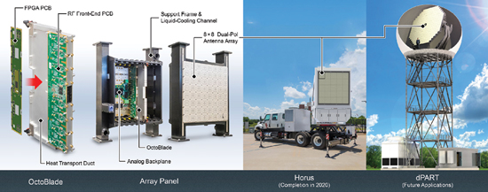
Figure 4 Electronics and 8x8 dual polarized panel (left); Horus truck with an array of panels (middle); future application that employs a multitude of panels and leverages the scalable architecture (right).
In general, the performance of large arrays depends on their digital interconnection structure on the backside of the array. Traditional and hierarchical topologies are currently in use, and their characteristics such as scalability, flexibility, high bandwidth, etc. are limited. For instance, some use a mesh topology. With a mesh topology, central channels are significantly burdened. This often leads to the congestion of the center area of the mesh. The solution for such a situation is to add routers in the mesh or to use torus topology which, with the symmetry introduced on the routers in the opposite edges, tends to mitigate unwanted congestion with a small increase of resources. Many open issues remain, and we believe that the three primary issues are: data transport mechanism (i.e., RapidIO, Gigabit Ethernet, etc.), degree of partial beamforming, and data routing topology (i.e., hierarchal, etc.). Balancing these issues will allow for array sizes to be conveniently scaled to meet a wide range of missions.
For normal radar operation of Horus, digital beamforming will be accomplished over a RapidIO network feeding the back of the panels. This will enable beam-bandwidth products for a notional multi-function PAR system (e.g., 200 MHz beams at suitable dynamic range). Hierarchical beamformers reduce the number of data streams at each level of the hierarchy, performing partial weighting and aggregation along the way. Systolic beamformers are similar, but instead of aggregating data in parallel at a given “stage,” data is sent serially down a link of nodes or even elements, with partial beam data being aggregated along the way to produce outputs for subsequent processing stages. Virtually every digital array of moderate-to-large size known to the authors uses some form of hierarchical/systolic processing to form digital front ends. Importantly, and unlike analog arrays, with hierarchical/systolic beamforming, the number of beams can be traded against the signal bandwidth in the digital domain, with a fixed overall “beam-bandwidth” product remaining roughly constant at every point in the front-end processing chain.
For multi-tier hierarchies, the interconnection costs scale with the logarithm of the number of elements M, while data and front-end processing scale roughly linearly with M. Both scale with the overall system bandwidth. These types of considerations guide the design of any front-end DBF architecture within the overall trade space of calibration, beamforming, and adaptation. Finally, RapidIO supports arbitrary network architectures, like folded-Torus, that can reduce latency and improve reliability, and these will be explored in the future.
Figure 5 shows the laboratory measurements for the mobile demonstrator.9 This fully digital active and dual-polarized phased array antenna was designed for full control of transmitted and returned signals of each antenna element. The antenna design for the ARRC’s project was focused on achieving the same or improved performance compared to WSR-88D parabolic antennas. These design specifications are critical, given that the weather mission presents more challenging polarimetric requirements, in terms of target identification, than those for aircraft surveillance missions. Dual-polarized radars require both low cross-polarization levels (better than −40 dB) and well-matched patterns (lower than 0.1 dB) to successfully determine the polarimetric variables of the scanned atmosphere sector.
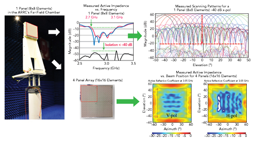
Figure 5 Experimental set-up and various parameter measurements.
In general, when the cross-polarization levels of the antenna increase, all the biases in the polarimetric variables are increased. Multiple factors in the antenna element were investigated during the design process of the 8x8 array, and these factors included: edge diffraction suppression; bandwidth in excess of 10 percent with a central frequency of 2.8 GHz; port-to-port isolation in the element on the order of −50 dB; cross polarization levels below −45 dB and co-polar mismatch below 0.1 dB at ±60° and ±10° for scanning range at the azimuth and elevation planes, respectively. After careful calibration; an active reflection coefficient of at least −10 dB at ±60° and ±10° can be achieved for scanning range at the azimuth and elevation planes, respectively. Consequently, a new stacked cross microstrip patch radiator with electromagnetic coupling was developed for Horus,9 and an 8x8 panel of these are depicted on the left side of Figure 5. The radiators and the feeding network were separated into two different assemblies to prevent them from bending after fabrication. The radiator assembly consists of two conducting layers and a radome of RT/Duroid 5880LZ bonded with RO4450F.
Modern day and next-generation radars are challenged to operate in complex, dynamic environments as demand for precious spectrum continues to grow. For instance, the desire for resilient systems that can adapt to and counter new sources of interference across the spectrum is a common theme that crosscuts the Army’s modernization strategy. Consequently, in order to mitigate interference, the integration of miniaturized filters, both static and frequency reconfigurable, into the antenna panels is being investigated in parallel with the antenna development. These filters are based on capacitively-loaded, substrate-integrated waveguide (SIW) resonators that are completely integrated into the feeding network assembly. The static filters provide added out-of-band rejection, and the reconfigurable filters can be used to achieve in-band interference rejection.10
PROJECT STATUS AND FUTURE R&D PLANS
This article provides a summary on a project that will provide solutions to modern-day radar challenges by delivering the full flexibility of digital at every element (i.e., digital Tx and Rx for both H and V on every element). The list below provides a concise summary of possibilities for demonstrations with the Horus system:
- Advanced aperture and waveform agility, performing many different tasks/objectives simultaneously;
- MIMO radar - multiple transmit and receive antennas;
- Spectrally agile active phased arrays;
- Advanced DBF for a higher angular resolution with wide coverage, which includes adaptive beamforming for improved interference and clutter suppression;
- Array imaging - efficient systems of reduced size and cost;
- Exquisite control of polarimetry: single H, single V, simultaneous H&V for slant 45, LHC, RHC or arbitrary polarization states; and
- In situ array calibration using the mutual coupling method.n
ACKNOWLEDGEMENTS
The authors thank the ARRC staff engineers for their dedication to the design and construction of Horus. This paper is based upon research supported by, or in part by the University of Oklahoma; the U. S. Office of Naval Research under award number N00014-18-1-2896; the NOAA/Office of Oceanic and Atmospheric Research under NOAA-University of Oklahoma Cooperative Agreement #NA11OAR4320072, U.S. Department of Commerce; and the Army Research Office under Agreement #W911NF-19-1-0046. The authors would also like to thank Boonleng Cheong for his assistance with the graphics. The views, opinions expressed and/or findings contained in this report are those of the author(s), do not necessarily represent the opinions of the U.S. government and should not be construed as an official U.S. government position, policy or decision, unless so designated by other documentation.
References
- R. Palmer, C. Fulton, J. Salazar, H. Sigmarsson and M. Yeary, “The Horus Radar - An All Digital Polarimetric Phased Array Radar for Multi-Mission Surveillance,” American Meteorological Society Annual Meeting, 2019.
- M. Peck, “Raytheon Takes FlexDAR Contract,” May 2014, http://archive.c4isrnet.com/article/20140505/C4ISRNET08/305050001/Raytheon-takes-FlexDAR-contract.
- C. Fulton, M. Yeary, D. Thompson, J. Lake and A. Mitchell, “Digital Phased Arrays: Challenges and Opportunities,” Proceedings of the IEEE 104, No. 3, 2016, pp. 487–503.
- C. Curtis, M. Yeary and J. Lake, “Adaptive Beamforming to Mitigate Ground Clutter on the National Weather Radar Testbed Phased Array Radar,” IEEE Transactions on Geoscience & Remote Sensing, Vol. 54, No. 3, March 2016, pp. 1282–1291.
- H. Bluestein et al, “Radar in Atmospheric Sciences and Related Research: Current Systems, Emerging Technology, and Future Needs,” Bulletin of the American Meteorological Society 95, No. 12, 2014, pp. 1850–1861.
- K. Hondl and M. Weber, “NOAA’s Meteorological Phased Array Radar Research Program,” IEEE Symposium on Phased Array Systems and Technology, October, 2019.
- G. Zhang, R. Doviak, D. Zrni, R. Palmer, L. Lei and Y. Al-Rashid, “Polarimetric Phased-Array Radar for Weather Measurement: A Planar or Cylindrical ConFiguration?” Journal of Atmospheric and Oceanic Technology 28, No. 1, 2011, pp. 63–73.
- B. Isom, R. Palmer, R. Kelley, J. Meier, D. Bodine, M. Yeary, B. Cheong, Y. Zhang, T. Y. Yu and M. Biggerstaff, “The Atmospheric Imaging Radar: Simultaneous Volumetric Observations Using A Phased Array Weather Radar,” Journal of Atmospheric and Oceanic Technology, Vol. 30, No. 4, April 2013, pp. 655–675.
- J. Diaz, J. Salazar-Cerreno Jorge Ortiz, N. Aboserwal, R. Lebron, C. Fulton and R. Palmer, “A Cross-Stacked Radiating Antenna with Enhanced Scanning Performance for Digital Beamforming Multifunction Phased-Array Radars,” IEEE Trans. on Antennas and Propagation, Vol. 66, No. 10, 2018, pp. 5258–5267.
- S. Saeedi and H. H. Sigmarsson, “Miniaturized Evanescent-Mode Cavity SIW Bandpass Filter with Spurious Suppression,” 2018 IEEE Radio and Wireless Symposium, pp. 234–236.