
0.8 mm Connectors Enable D-Band Coaxial Measurements
The evolution of electronics technology is driving communications data transfer rates, which means larger bandwidth. To get larger bandwidth, systems must move up in frequency, and moving up in frequency to get more bandwidth requires higher performance connectors.
W-Band applications, i.e., from 75 to 110 GHz, have grown significantly over the last few years, such as automotive radar and wireless communications backhaul. To support the development and production of these and future systems, broadband device characterization extending beyond 110 GHz, i.e., into D-Band, is required. To address this need, Anritsu has developed the first 0.8 mm connector.
For a new frequency band, connectors were historically created ahead of or in parallel with the test and measurement equipment supporting the applications. Connectors like K, V and W1 have enabled new test equipment capabilities. In some cases, the connector was developed first, with the equipment developed quite a few years later, like the 1 mm connector, which extended coaxial measurements to 110 GHz.
Typically, waveguide has been used for interconnections at the higher end of the frequency spectrum. Waveguide accomplishes the task of sending signals through devices with low loss; however, it is not the optimal solution. As a frequency-banded component, waveguide lacks the advantage of broadband frequency coverage and single-sweep measurements. Waveguide adds complexity for any measurement to characterize broadband performance from low frequency to mmWave frequencies past 110 GHz.
Coaxial connectors are preferred for interconnections, especially for test and measurement. They have advantages like single-sweep capability, ease of use for measuring and testing devices and frequency scalability. Coaxial connectors avoid impedance variations between interfaces, like coaxial to waveguide, which introduce uncertainty.
DESIGN CONSIDERATIONS
To understand the 0.8 mm connector design, consider the electrical and mechanical characteristics of a connector. IEEE P287 is the standard for precision coaxial connectors covering DC to 110 GHz, outlining the electrical and mechanical properties for connectors down to 1 mm. IEEE P287 does not currently define the 0.8 mm connector; however, because frequencies above 110 GHz will be important in the future, 0.8 mm will eventually be included in the spec. The electrical characteristics of a connector define the frequency coverage and impedance, while the mechanical characteristics address how the connector design supports repeatability and mating. Combined, these characteristics, which are generally listed in a technical datasheet, are important design considerations.
The upper frequency of a connector is determined by the equation

where fc is the air cutoff frequency, c is the speed of light (3 x 10⁸ m/s), ϵr is the relative permittivity, μr is the relative permeability and λc is the line length.1 For the 0.8 mm connector, fc is approximately 166 GHz, assuming a perfect air dielectric. This maximum frequency is hard to achieve; the actual usable frequency is a percentage of the ideal because the internal components of a connector introduce transitions between air and the various materials, creating resonances that degrades the upper frequency. Although the 0.8 mm connector does not have a defined maximum frequency, which is still to be specified, connectors operating to 145 GHz are commercially available. A summary of RF connector types, including the 0.8 mm, is provided in Table 1.2


Figure 1 1 mm (a) and 0.8 mm (b) connectors.
Impedance is a primary electrical requirement, because system performance is based on the ability to prevent or design around impedance mismatch. For connectors in this frequency range, 50 Ω is the standard impedance; designs must ensure that the connector and all internal parts are as close to this impedance as possible. Impedance must be well controlled for a connector that spans from DC to above 110 GHz. The center conductor and dielectric support beads play crucial roles keeping the impedance within an acceptable tolerance.
Most mechanical characteristics are defined by a connector standard, such as IEEE P287, which outlines the mechanical properties, such as coupling nut tolerances, line size and dimensions. The standard assures mechanical compatibility between connector manufacturers. While the general mechanical assembly is outlined, additional connector details are required to ensure good performance: slot-less or slotted, pre-alignment before mating and environmental classification based on the end product.
THE 0.8 mm CONNECTOR
Moving up in frequency past W-Band starts with the requirement that the new connector must provide low insertion loss with metrology-grade and mode-free performance to the desired upper frequency. This is not easy, requiring many design decisions. The 1 and 0.8 mm connectors are similar - they are very close in mechanical size and share many external physical similarities - however, there are many internal differences (see Figure 1). While some 1 mm technology could be leveraged, the 0.8 mm connector needed several new design elements to optimize performance.
In the frequency domain, a good interface should minimize insertion loss to minimally degrade the loss budget of a system. Unknown impedances between interconnects can cause reflections, affecting insertion loss even before the signal reaches the device being tested. The signal should be preserved between interfaces. Impedance variation is also an issue in the time domain, so the eye diagram of an interface should have an optimal opening to ensure a clear and undistorted signal. The eye diagram is a figure of merit for designers creating digital circuits operating to mmWave frequencies. Whether for RF or high speed digital, the connector should be designed and built to provide performance that makes the connector transparent in the measurement environment.
What does it take to get the connector’s upper frequency past 110 GHz with good impedance matching, metrology-grade performance and a mechanical design that makes it durable and performing well? It requires identifying the mechanical issues influencing performance above 110 GHz, quantifying and correlating simulations with fabricated connectors and exploring materials for novel new assemblies. Because the scope of the design is so wide, this article focuses on the mechanical issues and new assemblies.
CONCENTRICITY AND IMPEDANCE
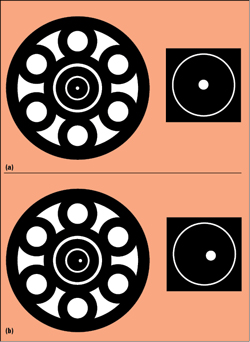
Figure 2 Male center pins: 100 percent concentric (a), not concentric (b).
Mating two connectors to pass signals is the starting point for transferring data, accomplished through a pin and slotted receptacle. Published literature describes various mechanisms for mating connectors to 110 GHz. Often, what is not described is that designers must account for repeatable and proper concentricity as the dimensions for both the pin and slotted receptacle get smaller. The performance of a connector is only as good as how well it mates with another connector. Concentricity describes how balanced and centered the male or female mating receptacle is. Ideally, the concentricity would be 100 percent. Without sufficient concentricity, proper mating will be impossible and damage to the connector inevitable (see Figure 2).
Concentricity is a mechanical parameter, and decisions to address it will affect the connector’s electrical performance. One approach to ensuring proper concentricity is evaluating the subassembly. For 1 mm connectors, the assemblies are threaded and easily manufacturable. The thread assembly removes the need for very fine tolerances. Concentricity, in this case, is trivial. Because the 0.8 mm connector requires accuracy over a broader frequency range - theoretically up to 166 GHz - tolerances cannot be relaxed. Assembly tolerance error will determine whether a pin or receptacle will sit perfectly in the center of the connector, so assemblies must account for this. Press fitting the 0.8 mm parts is the alternative to threaded assembly. Press fitting the connector allows for shorter connectors and improves concentricity, since the distance from the reference plane to the support bead is shorter.

Figure 3 A generic support bead (a) reflects the RF signal, while an impedance controlled support bead (b) minimizes reflections.
After changing assemblies from threaded to press fit for proper mating, the next obstacle is controlling the impedance, choosing the right internal components to keep the impedance close to 50 Ω. The 0.8 mm connector, like most high frequency connectors, has a center conductor requiring support beads, which is an integral part of the design for both the connector and housing. Several types of beads can support a connector’s center conductor, with various impedance profiles and dielectric signatures. The support bead must provide mechanical stability and minimize reflections through the connector. Support bead design is critical to the overall electrical performance, the key parameter being the impedance. The center conductor support bead, in the middle of the connector and in the path of the RF signal, has holes to simulate air dielectric. To minimally influence the signal passing through it requires a controlled impedance with tight tolerances, to get the support bead impedance as close to 50 Ω as possible to avoid reflecting signals and degrading performance (see Figure 3).
In the initial phase of creating the 0.8 mm connector, we tested various beads and found that many of them, including glass, have impedance tolerances of 5 percent of the nominal value. For a metrology-grade connector, impedance control must be better than 5 percent. This bead should be transparent to the measurement. After much testing and research, a proprietary, high temperature bead was developed that offers the desired performance: good VSWR and low insertion loss, as well as ensuring mechanical stability and environmental ruggedness. Using a proprietary Anritsu bead enabled an 0.8 mm connector with a typical insertion loss of 0.5 dB at 145 GHz.
Another design consideration is whether the connector should be compatible with 1 mm connectors. By choice, the 0.8 mm connector is not compatible with the 1 mm connector, as damage will occur when mating them. This was addressed by adding a fine thread to the connector to prevent the 0.8 mm from mating with a 1 mm connector, also preventing the connector from becoming loose during operation.
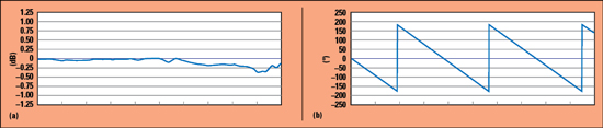
Figure 4 Measured insertion loss (a) and phase (b) of an Anritsu 0.8 mm female-to-female adapter, from 100 MHz to 145 GHz.
TESTING AND PERFORMANCE
After much design and evaluation, the finished 0.8 mm connector has a typical insertion loss of 0.6 dB from low frequencies to 145 GHz. After achieving this performance in the connector, Anritsu applied the same technology to cables and adapters. An 0.8 mm female-to-female adapter, tested with a 145 GHz vector network analyzer (VNA), has less than 0.5 dB insertion loss and linear phase response (see Figure 4).

Figure 5 90 Gbps eye diagram of the Anritsu 0.8 mm female-to-female adapter.
To assess the time domain performance for applications using an 0.8 mm connector to carry a digital signal, Figure 5 shows the eye opening of the same Anritsu female-to-female adapter with a 90 Gbps data rate signal; Figure 6 shows a 90 Gbps PAM 4 signal, both measured with a VNA with non-return-to-zero and PAM 4 eye diagram options. Both figures show excellent performance with high speed digital signals.
Figure 6 90 Gbps PAM 4 signal through the 0.8 mm female-to-female adapter.
AVAILABILITY
The 0.8 mm connector technology provides metrology-grade performance from DC to 145 GHz and is currently the only 0.8 mm connector on the market. Anritsu is integrating this platform in new components and test systems, such as screw-in sparkplug connectors, cables and test equipment. The 0.8 mm sparkplugs are pin and socket connectors covering DC to 145 GHz with 0.7 dB (typical) insertion loss. Anritsu has developed armored semi-rigid cables with 0.8 mm male-to-female connectors, available in 10 cm and 16 cm lengths. The cables have excellent insertion loss and return loss performance.
Anritsu test equipment with the 0.8 mm connector provides coaxial frequency coverage to 145 GHz. The VectorStar VNA with optional mmWave modules and 0.8 mm connectors covers from 70 kHz to 145 GHz with one sweep. An 0.8 mm calibration kit for the VectorStar VNA includes metrology-grade adapters and standards for the highest performance.n
References
- R. J. Collier and A. D. Skinner, “Microwave Measurements, Third Edition,” Stevenage: Institution of Engineering and Technology, 2007.
- B. Oldfield, “The Importance of Coax Connector Design Above 110 GHz,” Anritsu Co., 2007, https://dl.cdn-anritsu.com/ja-jp/test-measurement/reffiles/About-Anritsu/R_D/Technical/E-22/22_07.pdf.