Introduction
Signals in your noise can really mess up a design. They can impact communication performance or even cause you to fail EMC tests. Understanding what’s in the noise is becoming a more important part of designing products and wireless systems in the new digital age. For the detection, quantification, and classification of noise, we cannot rely on old tools and methods to give the insight needed to understand the hidden behavior of noise. The techniques used to detect noise and present information need a fresh new look. Modern analyzers and display technologies are now available to better detect and represent the types of noise that can impact EMI design and compliance, wireless communication systems, or in some cases show the mere existence of wireless devices.
In this column I will consider two of the most challenging problems in noise behavior: impulse noise and coexisting signals within noise. We will give some modern examples of how a new technique for examining noise can give you the necessary insight to avoid potential design or performance problems.
Impulse and tonal noise
Impulse noise has typically been related to a category of acoustic disturbance that occurs instantaneously (bursted). Characterized by sharp noises, this kind of noise can be traced to a multitude of phenomena in audio circuits: poor digital synchronization in recording, electromagnetic interference (from the vacuum cleaner), or if you are old enough to remember, scratches on the surface of the vinyl record.
Impulse noise is not limited to audio distortion. Software defined radios can often trace impulse noise to software errors in coding or filtering. Errors, when filtered, amplified, and transmitted, can generate blasts of energy around a wanted transmission. As it is broadband by its nature, impulse noise can impact adjacent receivers across a broad spectrum in a wireless design.
Impulse noise from electric motors in hybrid cars can create significant design challenges for the onboard electronics. The conducted and radiated noise from the electric motors can also impact the reliability of electronics that have not been designed to meet the immunity requirements necessary to function in this new environment.
Even some modern communication systems, like Ultra-wideband (UWB) WiMedia can resemble impulse noise. Bursting on and off in packets of 10’s of microseconds in bands of 500 MHz and changing frequency in around 70 nanoseconds.
Tonal noise can best be described as one or more continuous signals that does not appear to change frequency or amplitude over time. A continuous wave (CW) or sine wave signal is an example of tonal noise. Tonal noise is narrowband and can appear as a single or multiple spikes (“picket fence”) on a swept spectrum sweep.
class="storybodycaption">
Reply to this Article
Win: The first five contributors are eligible to receive a complimentary copy of the textbook Electrical Engineering – A Pocket Reference from Artech House.
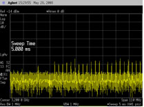
A traditional swept spectrum analyzer is less than ideal for the discovery and detection of impulse noise. While relying on a narrow resolution bandwidth envelope detector that is swept across a frequency, only the energy of the impulse that is present at the point in time of the sweep can be detected and displayed on the resultant trace. Have you ever seen “picket fences” on the display of a spectrum analyzer dancing across the display (see figure 1)? Did you ever change the sweep rate or resolution bandwidth and notice a change in the signal (change in amplitude or dancing in the other direction)? (See figure 2). If so, you had just experienced the challenge of trying to measure impulse noise with a traditional spectrum analyzer. If you tried to analyze the signal based purely on the captured waveform without changing sweep rates or resolution bandwidths, you might waste time chasing down what appears to be a multi-tone signal. Figures 1 and 2 show the resultant display of an Ultra-wideband signal with two different sweep rates in 1MHz resolution bandwidth. Looks more like a comb generator!

Figure 1) Impulse noise behavior looks like a “picket fence” dancing across the display from left to right

Figure 2) Now the signal looks different and moves across the display in the opposite direction
The swept tuned spectrum analyzer architecture does not provide a reliable way to discover the existence of this kind of transient signal, thus contributing to the long time and effort required to troubleshoot many modern RF signals. In addition to missing momentary bursted signals, the spectrum of impulse signals such as those used in modern communications and EMI may be misrepresented as well. Swept spectrum analyzer architectures cannot represent the occupied spectrum of a broadband impulse without repetitive sweeps and using the MAXHOLD trace information. Even using MAXHOLD, you still don’t know that it is not a multi-tone signal that changes frequency unless you are a skilled user of a swept spectrum analyzer.
Discrete Fourier Transform, DFT, based analyzers have the ability to represent a broad spectrum of signals instantaneously. By time-sampling a passband of spectrum and performing a rapid DFT on the sample data, the entire spectrum energy of an impulse signal can be displayed within a band of interest. DFT based analyzers can show the true spectrum of impulse energy and tonal energy at the same time!
Real-time display technology is now available to represent the spectrum information at a rate of over 48,000 times a second. This is fast enough to capture and display bursts of energy happening in the 10’s of microseconds. With this display technology, we can now provide tools to control the persistence and proportionality of a signal. As signals can turn on and off faster than the human eye can perceive, a persistence control enables a control on the duration or fade of the signal to allow the eye to detect events that would otherwise be too short to see. This provides insight to signals that are tough to isolate.
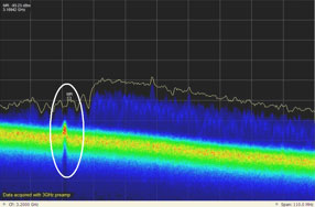
Proportionality allows us to grade (color grade) the occurrence of signals. In the figure 3, a temperature proportional scale is used to represent the frequency of occurrence. Red coloring represents the high proportionality of occurrence while blue coloring represents a lower (cooler) proportionality of occurrence.
As the UWB signal is an impulse type communication, we expect to see a low proportionality of the signal over a broad spectrum. This is shown in figure 3 on the left two thirds of the display. However, by analyzing the noise, pay particular attention to the part of the display circled on the left-hand side of Figure 3. This UWB device has a low level tonal emission signal within the sideband of the impulse spectrum that is on all the time. Notice the red (high proportionality) of the signal above the noise threshold, and the discontinuity in the baseline noise of the measurement system. This is not so obvious looking at Figures 1 and 2.

Figure 3) DFT analyzer with real-time display of UWB signal quickly demonstrates broadband nature of signal and discovers other noise products.
Discovering low level signals rising out of the noise and being able to rapidly distinguish between impulse and tonal noise are an essential capabilities for classifying noise. A tonal emission could eventually cause a product to fail a transmitter emission mask is the variables are not controlled or understood. If you take two spectrum analyzers with the same resolution bandwidths and RF performance, the noise behavior of the DFT analyzer will show you signal behavior in the noise 10-20 dB before you can see the signal in the noise of the swept spectrum analyzer.
Coexisting signals
Signals often coexist in the frequency domain. An example in the unlicensed ISM band is the coexistence of Wireless LAN and Bluetooth.

Figure 4) – Picture of coexistent technologies of Bluetooth and Wireless LAN
While often referred to as looking at signals-within-signals, unless you look at the specific band over time, the human eye is not fast enough to determine whether a Bluetooth signal, hopping frequencies at a rate of about 659 us is colliding with a Wireless LAN signal that might be on for 10 ms. However, a real-time display like that shown in Figure 4 can provide immediate insight to potential problems of coexistent wireless technologies. To see the occupied spectrum over time, you must view a Spectrogram.
An example of a coexisting noise in most every electronic device can be the unintentional radiated emissions, or EMI. Modern EMI suppression techniques make extensive use of clock dithering, or spread spectrum clocking. System clocks can typically withstand a few fractions of a percent of intentional slewing without impacting timing performance. At the same time, the resultant spectral emissions are greatly reduced within a specific occupied spectrum and the unintended radiated emissions can be spread over a broad spectrum.

Figure 5) – The PEAK trace (BLUE) and AVERAGE trace (YELLOW) of a dithered clock unintentionally radiating from a board.
Figure 5 shows a typical display that might be able to be seen using a traditional spectrum analyzer. With MAXHOLD, we can see the PEAK signal of interest over a specific span. Using a second trace to AVERAGE the signal, we notice an expected improvement for this particular measurement.
But, what’s really there?

Figure 6) Real-time proportional display of dithered clock and other emissions
Using real-time display technology, we can quickly and clearly see the other host of clock signals from other undithered sources hidden beneath the dithered clock spectrum. As these signals are predominately tonal emissions, note the red proportionality for the signals circled in Figure 6 and the fact that no signals appear beneath the red tones (the signals don’t go away!), these signals are not likely to benefit from standard detector methods like the Quasi-peak detector used for many EMI measurements.
Figure 6 can simultaneously display the broadband dithered signal and the tonal emissions coexisting because the signals do not always occupy the same frequency at the same time. From a design perspective, understanding the power contribution of from all the radiated sources is essential to proper EMC design. You now have a tool to discover coexisting signals quickly.
To understand how the signals behave over time, it is necessary to observe the spectrogram display. The spectrogram display shows the Frequency vs Time Vs Amplitude where the frequency is represented on the x-axis and time on the y-axis. The power is expressed by a color intensity chart similar to the proportionality grading of the real-time spectrum display.
As you can see in Figure 7, while the dithered signal varies in frequency over time, the two tonal signals do not. At the points of transition where the tonal signals and the dithered signal occupy the same frequency, the power of those events increases as does the intensity of the spectrogram color grade scale.

Figure 7) Real-time display and spectrogram of the same signal
Summary
Modern DFT-based spectrum analyzers can now detect and present the true spectrum behavior vital to the design, development, and implementation of wireless communication. Determining whether a signal is impulse noise or a tonal signal, or whether there are signals-within-signals are now intuitively obvious to the causal observer.
The days of having to be an instrument guru to figure out what you are actually seeing can be put behind us. The real-time display technology can accurately represent signals with live viewing. Interpreting the signals in the noise is simplified.
If I think about how much time I wasted in the EMI lab trying to decode those strange signals that appeared on my swept spectrum analyzer, I would be embarrassed to tell my boss why it took so long. The time and cost would have been better spent getting the proper tool for the job.
To find out more about real-time display technology from Tektronix and see the latest videos, visit www.tektronix.com
