
When designing multi-octave high-power amplifiers, it is a challenge to achieve both broadband gain and power matching using a combination of lumped and distributed techniques. One approach to overcoming this challenge is to design the power amplifier (PA) using load line methods combined with a novel coaxial impedance transformer with ferrite beads. This approach relies on accurate, linear and nonlinear models as the basis for all components. This article focuses on the design of a single-stage, 10 W PA with broadband performance from 30 MHz to 1 GHz. This design utilizes the Qorvo QPD1010 GaN high electron mobility transistor (HEMT).
The PA design used several software tools and models. The design software employed was Microwave Office for RF and microwave circuit design and Analyst™ for 3D EM finite-element method (FEM) analysis. Both of these programs are contained within the Cadence® AWR Design Environment® software tools. In addition, Modelithics models were used for the QPD1010 transistor and all surface-mount passive components.

This design requires a coaxial line combined with ferrite beads/cores impedance transformer to achieve the desired performance at the specified frequency range with the selected transistor. Although many amplifiers have been designed with these types of transformers, only those with downward impedance transformations have typically been documented. The transformer is designed using the Analyst 3D EM analysis tool.
DESIGN GOALS
As stated, the goal is to design a PA that operates from 30 MHz to 1 GHz. The PA must deliver at least 9 W of output power (Pout) over this operating frequency range with a Class AB bias condition. The power gain (Gp), defined as the gain at saturated output power, must be at least 12.5 dB. Finally, the gain flatness must be no more than ±0.5 dB and the input return loss must be at least 15 dB. These design goals are listed in Table 1.
DESIGN PROCESS
The following section describes the PA design process in more detail.
The Intrinsic Load Line Design Approach
The transistor’s I-V curves reveal that the intrinsic impedance (the fundamental frequency load line) needed for maximum power must be approximately 100 Ω or more.1 Figure 1 shows the transistor I-V curves and it defines the optimum load line graphically.

Figure 1 Approximate load line for maximum power.
The schematic shown in Figure 2 is used to determine the load lines that correspond to an impedance transformation of 2.25x greater than 50 Ω at the output of the transistor across the operating frequency range. The simulation is only performed with the fundamental tone, which can be selected from Options within the schematic.
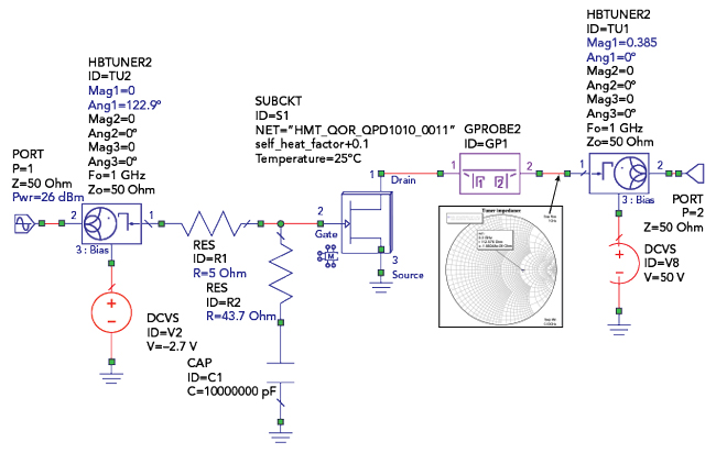
Figure 2 This schematic diagram for the load lines across the required bandwidth.
The load line (the intrinsic drain dynamic impedance) can be observed because the Modelithics model for the QPD1010 GaN transistor allows the designer to analyze the voltages and currents inside the model, specifically across the intrinsic generator. The Modelithics transistor model with access to intrinsic voltages and currents is shown in Figure 3.
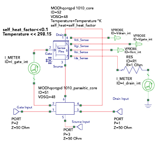
Figure 3 The Modelithics transistor model.

Figure 4 The simulated fundamental frequency load lines.
Figure 4 shows the I-V curves and the initial load line results obtained after simulating the schematic of Figure 2. The fundamental frequency load lines across the bandwidth fall into the appropriate region for good performance. Additional matching networks can be implemented to make the dispersion of the load lines appear even tighter.
The Coaxial Transformer
As discussed above, the relatively new 10 W, 50 V GaN HEMT requires an upward impedance transformation to achieve the optimal fundamental frequency load line. In this case, the transformer must have an impedance transformation ratio of 1:2.25.2 Employing a coaxial line with a ferrite core impedance transformer allows for better performance in terms of gain flatness and power over multi-octave bandwidths for applications below 1 GHz compared with matching networks that consist of reactive components.