For a modern radar sensor with an antenna array receiver front-end, the azimuth (and sometimes the elevation angle) is estimated from phase and amplitude information using digital beamforming on the receive side. To get the best azimuth measurement accuracy, every radar sensor needs to be adjusted. The following procedure is typical for radar calibration. First, the radar sensor is mounted on a turntable in an anechoic chamber. A corner reflector in the far field at a known distance is commonly used as a reference target. The radar pattern is then measured and flashed into the radar sensor’s memory. Later, this information is used by the detection algorithm. This ensures high azimuth measurement accuracy when the radar sensor completes production. The car manufacturer integrates this calibrated radar sensor into the car, often behind an emblem or the bumper, where the radome material influences the RF attenuation. The radome’s transmission loss increases the two-way attenuation of the radar signal, which reduces the maximum detection range of the radar. The power level of a transmitted radar signal is reduced by the range, R, to the target and by R4 on the return. For a 77 GHz radar system with 3 W output power, 25 dBi antenna gain, a target with a 10 m2 radar cross-section and a minimum detectable signal of ‐90 dBm, the maximum range would be 109.4 m, according to the range equation. If the radome has 3 dB two-way attenuation, the maximum range of the same radar measuring the same target would decrease to 92.1 m. That is approximately 16 percent less range.

Figure 3 Inhomogeneous radome material causes planar wave distortion and attenuation, leading to azimuth errors and reduced detection performance.
It is not only material attenuation that has a great impact. The material reflectivity and homogeneity also play important roles. Reflections and RF mismatch of the material cause direct signal reflections in close range to the radar. The signals are received and down-converted in the receiver chain, reducing the radar’s detection sensitivity. Many car manufacturers try to mitigate this effect by tilting the radomes—not only for design reasons—to reflect the transmitted radar signal somewhere other than directly back into the receiver front-end. This solution, of course, has mechanical limitations, not to mention the expected loss of RF energy from these parasitic reflections. Another problem comes from material inhomogeneities that disturb the echo signal wavefront used to estimate the azimuth value. Inhomogeneous material distorts the wavefront, which results in less accurate angular measurements.
The radar sensor calibration is no longer sufficient, since the previously calibrated radar can be mounted behind any indeterminate radome from a different manufacturer (see Figure 3).

Figure 4 Testing with a golden radar identifies some errors and signal degradation caused by the radome.
MATERIAL CHARACTERIZATION
Radome manufacturers typically test their units with a known or “golden” radar. For this test, several corner reflectors are mounted in front of the radar at predetermined ranges and azimuth positions (see Figure 4). A differential measurement is conducted with and without the radome, and these measurements are compared. For the radome to pass the test, the range/azimuth positions and echo signal levels must be within defined limits. However, this approach only tests certain azimuth angles and does not account for possible inhomogeneity or blind spots.
Another measurement method relies on a functional test. The radar sensor with the radome is mounted on a turntable and a corner reflector is placed in front of them. By turning the complete unit, every azimuth and elevation angle can be measured and compared to the radar-only standard. This method is as accurate as the positioning of the turntable; however, the test takes a long time and is not feasible for production tests.

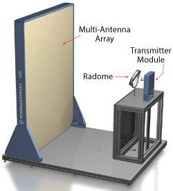
Figure 5 Radome test using the R&S QAR system.
Instead of testing transparent radar material with a golden device, a proposed novel measurement method combines a transmission measurement with three-dimensional, high resolution radar imaging in the 77 to 79 GHz frequency band used by the radar itself. This is done using the R&S QAR system (see Figure 5). A multi-antenna array consisting of several hundred transmit and receive antennas operating from 75 to 82 GHz is used. This measurement system can measure the range, azimuth and elevation with millimeter resolution. It operates in the same frequency band as the automotive radar and “sees” what the automotive radar would see if it also had hundreds of transmit and receive antennas. Thanks to the large aperture, the resolution of the test system is much higher than that of the automotive radar, and it can visualize the measurement as an image. The radome is placed in front of the test system, which performs a two-stage measurement.
Reflectivity
First, a reflectivity measurement determines the amount of energy reflected by the radome material; this is energy that does not pass through the radome and contributes to performance degradation. Reflected signals decrease the performance of the radar and can even interfere with the received signals. Areas with high reflectivity can have various causes, such as material defects, air gaps, undesired interaction between layers of material, excessive amounts of certain materials or foreign objects. The measurement method achieves a spatially resolved reflectivity measurement for a radome by linking the information collected by the distributed, coherent transmit and receive antennas. The receive signals are gated and processed for all receive antennas, which results in a high resolution 3D radar image. The resulting mmWave image enables intuitive as well as quantitative evaluation of the radome’s reflection behavior.

