

The measurement of balanced devices uses a two-port vector network analyzer (VNA) and a pair of baluns. A method for de-embedding the baluns using the built-in de-embedding feature of the VNA is described.
Balanced measurements are necessary for many applications. High speed digital transmission lines are often employed on printed circuit boards to transport signals with extremely high bandwidths. It is important to be able to verify insertion loss, characteristic impedance, phase imbalance and cross talk to adjacent conductors. Antennas are sometimes fed with balanced lines as well, and being able to verify the return loss or VSWR of the balanced feed plus antenna combination is useful.
USING A VNA FOR BALANCED CHARACTERIZATION
A vector network analyzer makes only unbalanced measurements. That is, each port sends and receives signals on a coaxial cable where the RF excitation signal and any reflections progress on the center conductor and the equal and opposite return signal is carried on the inside of the coaxial shield (see Figure 1). No RF current should flow on the outside of the shield.
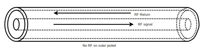
Figure 1 Coaxial RF current flow.
As a side note, we rarely think about the return path on the inside of the shield. Consider that there is no net magnetic field generated by the cable since the two signals have opposing fields and cancel. Therefore, it is possible to clamp a ferrite core on the outside of the cable to prevent externally induced RF from traveling on the outside of the shield. If the two currents did not cancel, the ferrite would make the center conductor unacceptably inductive, but because they do, there is no net effect on internal signal propagation.
Because the VNA does not generate a balanced drive signal, it is necessary to use two ports to measure a balanced input or output. For example, in Figure 2, one side, “A,” of the input is driven by port 1, while port 2 maintains a 50 Ω termination on side “B.” “B” is then driven by port 2 and “A” is terminated by port 1. The two unbalanced measurements may be combined to calculate the effective balanced response. It is important to note that this method only works with a passive, linear device under test (DUT). An active differential device may not exhibit linear behavior if only one input is driven at a time. In that case, the linear combination of one driven input with the other port terminated will not likely be the same as the case where both inputs are driven simultaneously with a balanced drive.
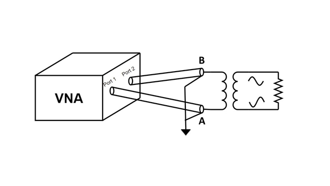
Figure 2 Measuring a balanced input.
For a differential measurement, the A/B terminals of the DUT are called differential port 1. This can be confusing, but differential port 1 S-parameters are derived from the unbalanced measurements from VNA ports 1 and 2.
For example, the calculation for the input Differential S-parameter of the DUT in Figure 2 is:
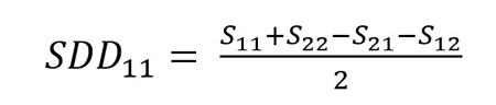
(The 11 subscript on SDD refers to the A/B differential port 1, not port 1 of the VNA) The differential input looks like the sum of the two-port reflections A and B minus the two cross terms between them.
The two-port VNA software, “S2VNA” from Copper Mountain Technologies does not have this measurement conversion built-in, but data can easily be taken using standard commands for programmable instruments (SCPI) and processed to produce differential S-parameters.
As a further example, the differential “insertion loss”1 through the differential device, or SDD21, requires a 4-port measurement (see Figure 3). Differential return loss is found by Equation (1) and insertion loss is:
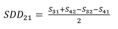
With appropriate unbalanced measurements, it is, therefore, possible to determine balanced performance.
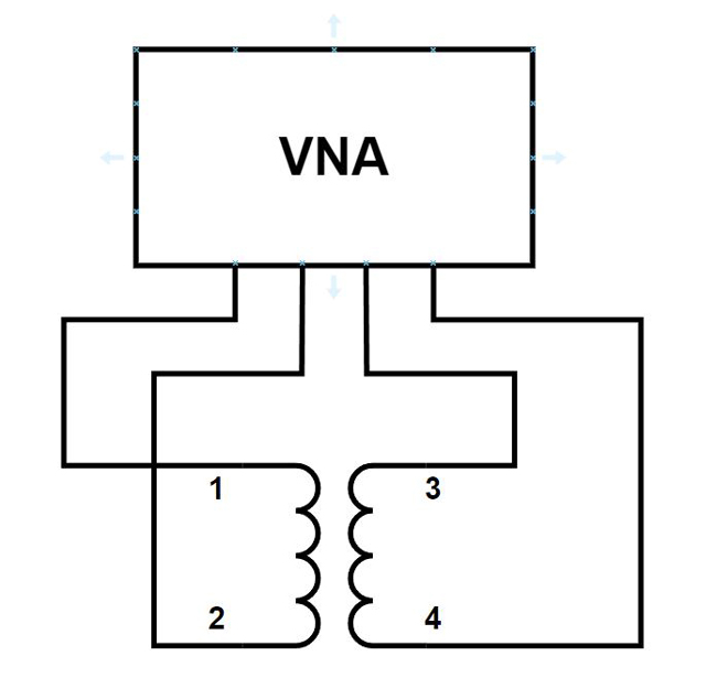
Figure 3 Full balanced measurement of a DUT.
BALUN TYPES
There are two types of baluns: voltage and current (see Figure 4). A voltage balun forces the balanced output to have equal and opposite voltages. The two currents are not necessarily balanced. A current balun forces the balanced output currents to be equal and opposite2.
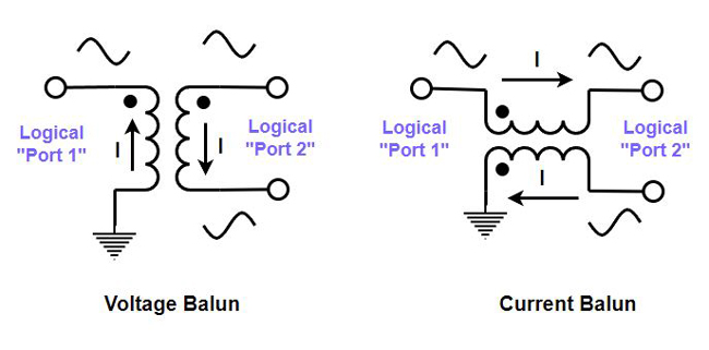
Figure 4 Balun types: voltage and current.
The voltage balun generates balanced voltage outputs, acting as a transformer. It will not operate well at low frequencies where coupling is reduced and resonance with interwinding capacitance limits its high frequency response. The current balun can generally operate over a wider bandwidth and produces a balanced output current by virtue of magnetic coupling presenting a high impedance to unbalanced currents. At low frequencies, the signal may pass through the chokes, but common-mode rejection will be poor. Resonance at high frequencies is also an issue. There are a great number of balun types and configurations, but the focus here is the characterization of a balun for use with a two-port VNA.