BALUN CHARACTERIZATION
A Balun, which is a contraction of the words balanced and unbalanced may be attached to a VNA port to convert the unbalanced port for a balanced measurement. With two baluns, a two-port VNA can make fully balanced measurements of passive or active devices. For accurate measurements, the baluns must be fully characterized, and their effects removed (de-embedded) from the measurement to ascertain the response of the DUT alone.
Before proceeding, it is important to understand the mixed mode S-parameter measurements which apply to a balun. A balun has a single-ended (SE) port on one side and balanced (Bal) port on the other.

Figure 5 Balun ports.
Port 2 in Figure 5 has two components. One component is the balanced signal where the phase difference is precisely 180 degrees between the two connections of the port. The other component is the common-mode signal where the phase is zero degrees between the two connections. A perfect balun creates only a balanced signal on port 2 if excited by a signal on port 1. No common-mode (in phase) signal is generated.
No balun is perfect, however, and there is always a combination of both. Note that any small phase shift introduced on either of the differential outputs will create a small common-mode component on that port, an effect particularly noticeable at higher frequencies. Proper PC layout with trace length matching is therefore important for the printed circuit board layout of a surface-mount balun. Mixed mode parameters for a balun are defined in Table 1.

These mixed mode parameters define all differential and common-mode effects of the balun:
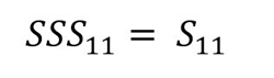
SSS11 is the return loss looking into the SE Port 1.
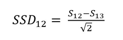
SSD12 is the SE signal developed on Port 1 from the balanced signal on port 2.
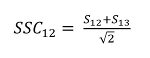
SSC12 is the SE signal developed on port 1 by the common-mode signal on port 2. This should be a very small number for a good balun.
SDS21 is the differential “thru” response of the balun.
SDD22 is the differential port 2 return loss.
SDC22 is the differential mode reflection from Port 2 due to a common-mode excitation.
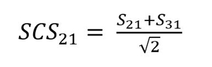
SCS21 is the common-mode signal generated on port 2 by the SE port 1 input. This should be very small for a good balun.
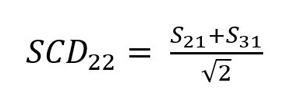
SCD22 is the common-mode reflection from Port 2 due to a differential mode excitation.
SCC22 is the common-mode reflection from Port 2 due to a common-mode excitation.
Additional figures of merit for a balun are its common-mode rejection ratios in each direction:
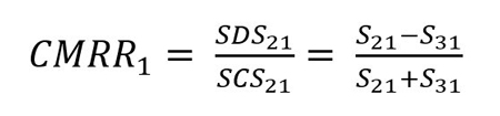
CMRR1 = SDS21/SCS21, the ratio of the differential to common-mode signal generated on Port 2 by a signal on Port 1
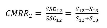
CMRR2 = SSD12/SSC12, the ratio of the SE signal generated on Port 1 by a differential signal on Port 2 to the one created by a SE signal on port 2.
Both common-mode rejection ratios should be reasonably large numbers for a good balun. A ratio of 10 or more (linear magnitude) is reasonable.
All mixed mode characteristics may be calculated from a three-port measurement of the device.
MIXED MODE PARAMETER CALCULATION FROM UNBALANCED VNA MEASUREMENTS
For measurement, the balun is connected to the VNA as shown in Figure 6. The diagram depicts a voltage balun, but the configuration is unimportant. It is simply assumed that port 1 goes to the unbalanced Logical Port 1, and ports 2 and 3 are attached to balanced Logical Port 2.

Figure 6 Balun connections.
In the following formulas, port numbers 1, 2, and 3 are used for the VNA S-parameter subscripts and the mixed mode S-parameters like SDD22 are designated by logical ports 1 and 2. A full 3-port measurement of the balun is required, but this could be performed two ports at a time with a two-port VNA while terminating unused ports with a 50 Ω load. The mixed mode S-parameters are calculated as follows:3