
Frequency conversion is at the heart of many modern communication systems. At its most basic level, a frequency converter requires a low noise local oscillator (LO) with a phase locked loop and an up/down-conversion mixer. Excellent phase noise, low spurious levels and a mixer with high IIP3 are key requirements for high performance converters that can frequency translate highly complex input signals carrying multiple channels and modulations. Designing a frequency converter for battery powered applications adds the extra challenge of low voltage operation and low current consumption in order to maximize battery life.
The RF2054 IC addresses these market requirements. It can be used as a 2.2 V frequency converter which is ideal for use in battery-powered wireless, consumer and professional devices. The RF2054 belongs to a family of wideband integrated frequency converters available from RFMD that support RF/IF frequencies from 30 to 2500 MHz.
Figure 1 shows that the RF2054 IC contains two Gilbert cell mixers, a fractional-N synthesizer, a voltage controlled oscillator (VCO) and reference oscillator circuitry. This is all integrated in a 5 × 5 mm QFN package. The VCO can be tuned to cover a specific frequency range by selecting the appropriate value of external inductors. Sharing the same LO frequency, one mixer can be used for up-conversion and the other mixer for down-conversion making the RF2054 a very compact, single-chip frequency converter or band-shifter. Alternatively, the two mixers could both be used for down-conversion in order to implement a highly integrated diversity receiver.
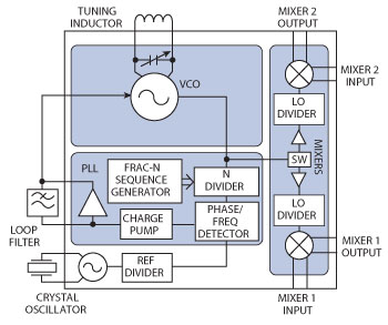
Figure 1 Block diagram of RF2054.
The fractional-N synthesizer in the RF2054 takes advantage of an advanced third order sigma-delta modulator that delivers ultra-fine step sizes and low spurious products. The integer boundary spurs are typically below –55 dBc. The fractional-N synthesizer also has the advantage of fast lock times; the synthesizer can be configured to lock within 40 µs of enabling the device. Another feature of the synthesizer is the on-chip crystal sustaining circuit with programmable loading capacitors. This allows a crystal of between 10 and 26 MHz to be used for the reference, and by programming the correct load capacitance, the frequency error can be minimized. Using a standard low cost crystal in this way minimizes the total solution cost, and saves on the added current consumption of an external crystal oscillator circuit, typically 2 mA. Alternatively, an external reference of between 10 and 104 MHz can be used.
The VCO is a differential structure and the tuning range is defined by the value of two external inductors in parallel with a bank of switched capacitors integrated into the VCO resonator, which give 128 overlapping bands. These are used to achieve a tuning range of up to 40 percent whilst maintaining low VCO tuning gain (MHz/V) and optimal phase noise performance across the entire VCO frequency range. The chip automatically selects the correct VCO band (VCO coarse tuning) for the programmed frequency when the device is enabled. The LO frequency range is extended further using high frequency dividers between the VCO output and mixer LO ports. These LO dividers can be bypassed or set to divide by 2 or 4.
The normal power supply range specified for the RF205x family of frequency converters is +2.7 to +3.6 V. The RF2054 is a variant suitable for operation at +2.2 V. Dropping the supply voltage extends the battery life and reduces the current draw in the chip with only marginal degradation in performance. Using an external inductor, the VCO can be tuned to run at the LO frequency of choice without using the LO dividers, further minimizing the current consumption. The mixer bias can also be set to give low current operation at the expense of linearity.
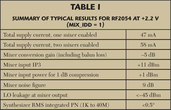
To evaluate the RF2054 at +2.2 V, measurements were made with a frequency plan selected to demonstrate the performance at typical RF, IF and LO frequencies. An RF input of 900 MHz was chosen, down converting to an IF output of 70 MHz. Most of the measurements made concentrated on the requirement for low power, so used the lowest mixer bias current setting, MIX_IDD = 1. A standard RF2056 evaluation board was used with some minor modifications as noted. The device was programmed using the “RFMD Slice Programming Tool” graphical user interface (GUI). The RF2056 design kit (evaluation board plus interface cables) and the GUI are available at www.rfmd.com/products/IntSynthMixer.
The evaluation board uses an FTDI UM232R USB-to-serial adapter to enable the RF2054 to be programmed from a PC running the GUI. The UM232R adapter is normally set for 3V3 logic. The limit on the RF2054 for the logic high input voltage is Vdd +0.3 V. So for supply voltages below +3 V, the logic high level needs to be reduced. This is easily done by connecting the VIO pin on the UM232R adapter to the evaluation board power supply.
To achieve a high side LO frequency of 970 MHz, two 3.3 nH inductors were used in the differential VCO resonator circuit. These set the VCO frequency range between 850 and 1200 MHz, with the required frequency of 970 MHz coming out near center in the VCO coarse tuning range.
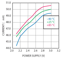
Figure 2 Total supply current, single mixer enabled vs. temperature and supply voltage.
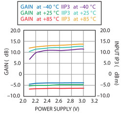
Figure 3 Mixer conversion gain and IIP3 vs. temperature and supply voltage.
The results of this evaluation, summarized in Table 1, show that the RF2054 can be operated satisfactorily with power supply voltages down to +2.2 V. Lowering the supply voltage from +3 down to +2.2 V reduces current consumption by around 4 mA as shown in Figure 2. This results in a significant drop in power consumption that has little impact on performance. Figure 3 shows that the mixer gain and linearity fall slightly, the input IP3 is reduced by 1 to 2 dB. The synthesizer and VCO phase noise are unaffected. It is not recommended to operate the RF2054 at below +2.1 V.
Operating the RF2054 with the synthesizer and one mixer enabled, at +2.2 V consumes a total power of typically just 105 mW, and with both mixers enabled 130 mW. This represents a 30 percent reduction in power consumption compared to the nominal +3 V supply, making the RF2054 ideal for low power applications.
RFMD,
Greensboro, NC
www.rfmd.com
sales-support@rfmd.com